Microprocessor Controller for DOAS 31
®
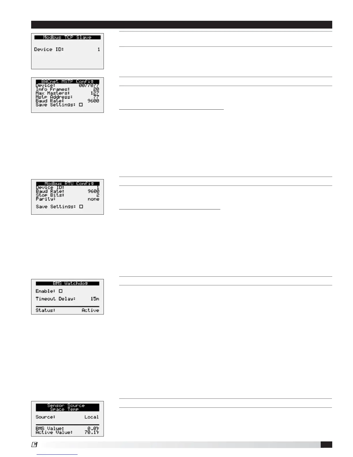
THIS SCREEN ALLOWS THE USER TO ADJUST BACNET AND MSTP PARAMETERS.
This screen only appears if the selected BMS protocol is set to BACnet MSTP.
Factory settings are shown in the screen to the left.
To change BACnet MSTP parameters:
1. Power on the controller and allow several minutes to initialize.
2. Go to Network Settings menu and view BACnet MSTP Config screen.
3. Move cursor to desired parameter by pressing the enter button. Press up and
down arrows to adjust the parameter. Press enter to accept adjusted value.
4. Once desired parameters have been entered, enable the ‘Save Settings’ option
and press the enter button.
5. Reboot the controller by cycling power to the unit. Allow several minutes for the
controller to initialize.
6. View BACnet MSTP Config. If changed values did not save, contact the factory.
THIS SCREEN ALLOWS THE USER TO ADJUST MODBUS PARAMETERS.
This screen only appears if the selected BMS protocol is set to Modbus. Factory
settings are shown in the screen to the left.
To change Modbus RTU parameters:
1. Power on the controller and allow several minutes to initialize.
2. Go to Network Settings menu and view Modbus RTU Config screen.
3. Move cursor to desired parameter by pressing the enter button. Press up and
down arrows to adjust the parameter. Press enter to accept adjusted value.
4. Once desired parameters have been entered, enable the ‘Save Settings’ option
and press the enter button.
5. Reboot the controller by cycling power to the unit. Allow several minutes for the
controller to initialize.
6. View Modbus RTU Config. If changed values did not save, contact the factory.
THIS SCREEN ALLOWS THE USER TO ENABLE THE BMS WATCHDOG FUNCTION.
The BMS watchdog function verifies BMS connectivity. The watchdog is required
for the BMS to take the place of a hardwired sensor. The BMS toggles the
watchdog variable from true to false within the timeout delay. If the timer expires,
the controller falls back to hardwired sensors until the BMS connection can be
established. At this time, a BMS watchdog alarm activates.
The following variables may be used by the BMS in place of hardwired sensors:
• Outside_RH_from_BMS
• Outside_Temp_from_BMS
• Return_RH_from_BMS
• Return_Temp_from_BMS
• Space_1_CO2_from_BMS
• Return_CO2_from_BMS
• Space_RH_from_BMS
• Space_Static_from_BMS
• Space_Temp_from_BMS
SENSOR SOURCE SPACE TEMP
The sensor source can be changed to source by BMS through the controller or by
a dedicated BMS point. Reference Points List above and in the Appendix for more
detailed point information. Screen to the left is an example of the sensor source
type. Source can be set for local or BMS at this screen.
Menu
THIS SCREEN ALLOWS THE USER TO VIEW AND ADJUST CONTROLLER MODBUS TCP
S
LAVE.
This screen will appear if the unit is set for Modbus TCP and allows the user to set
device ID number.