Greenlee / A Textron Company 23 4455 Boeing Dr. • Rockford, IL 61109-2988 USA • 815-397-7070
881 and 881CT Cam Track
®
Hydraulic Benders
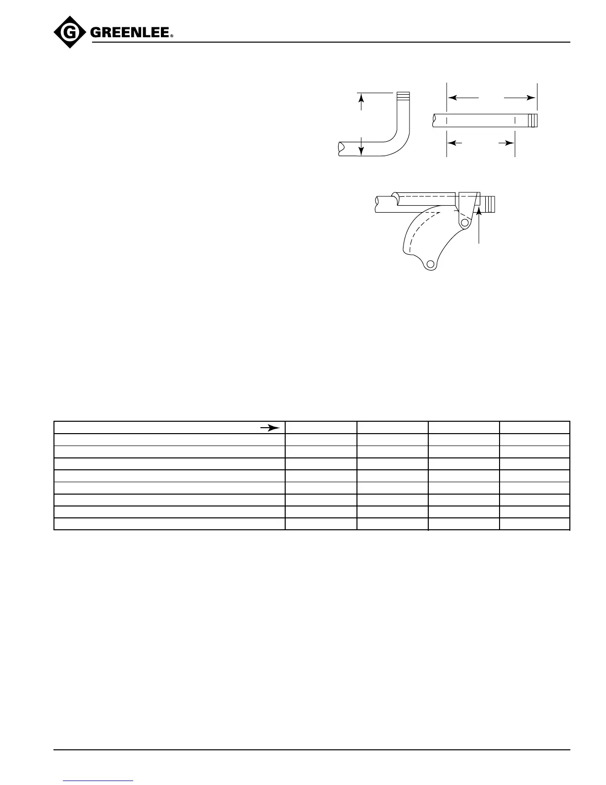
Laying Out One-Shot 90° Bends
1. Measure the length of the required stub.
2. Find the Minimum Stub Length on the Table 2:
Deduct, Stub Dimensions, and Minimum Distance
from End of Conduit. The stub you require must be
equal to or longer than the minimum stub length.
3. Measure and mark the stub length on the conduit.
This is Mark 1.
4. Find the Deduct on Table 2. Subtract the Deduct
from Mark 1 and make a new mark. This is Mark 2,
or the bending mark. Find the Minimum Distance
from End of Conduit in Table 2; be sure that Mark 2
is at least this distance from the end of the conduit.
5. Align Mark 2 with the outside edge of the saddle.
Bend the conduit—see the instructions under
Assembly and Operating Instructions.
MARK 1
MARK 2
MARK
2
STUB LENGTH
TO BOTTOM
OF CONDUIT
DEDUCT
STUB
LENGTH
CONDUIT SIZE 2-1/2 3 3-1/2 4
EMT
Deduct 21-1/2 24 27-3/4 32-1/4
Minimum Stub Length 24 27 31-1/4 36-1/4
Minimum Distance from End of Conduit 2-1/2 3 3-1/2 4
IMC-RIGID
Deduct 21-1/2 24-1/4 28-1/4 32-1/2
Minimum Stub Length 24 26-3/4 30-3/4 35
Minimum Distance from End of Conduit 2-1/2 2-1/2 2-1/2 2-1/2
Table 2
Deduct, Stub Dimensions, Minimum Distance from End of Conduit