Greenlee / A Textron Company 6 4455 Boeing Dr. • Rockford, IL 61109-2988 USA • 815-397-7070
881 and 881CT Cam Track
®
Hydraulic Benders
Assembly and Operation Instructions
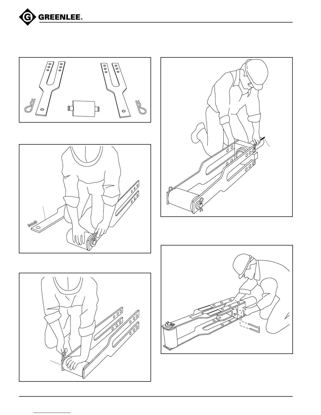
881 and 881CT—Floor Operation (refer to Identification—Major Components)
1. Lay out the connecting bars (C), roller unit (D), and
two hitch pin clips (E).
CONNECTING BAR
WITH BENDING
INSTRUCTIONS DECALS
2. Attach the roller unit to one of the connecting bars
with a hitch pin clip, as shown.
3. Repeat Step 2 for the other connecting bar.
DECALS
FACE OUTWARD
4. Position the ram and cylinder block so that, from the
operator’s point of view, the ram scale is up and to
the left of the ram.
5. Attach the yoke (B) to the ram with the spring clip (H).