Greenlee / A Textron Company 11 4455 Boeing Dr. • Rockford, IL 61109-2988 USA • 815-397-7070
881 and 881CT Cam Track
®
Hydraulic Benders
Assembly and Operation Instructions
881 and 881CT with 1813 Bending Table (refer to Identification—Major Components)
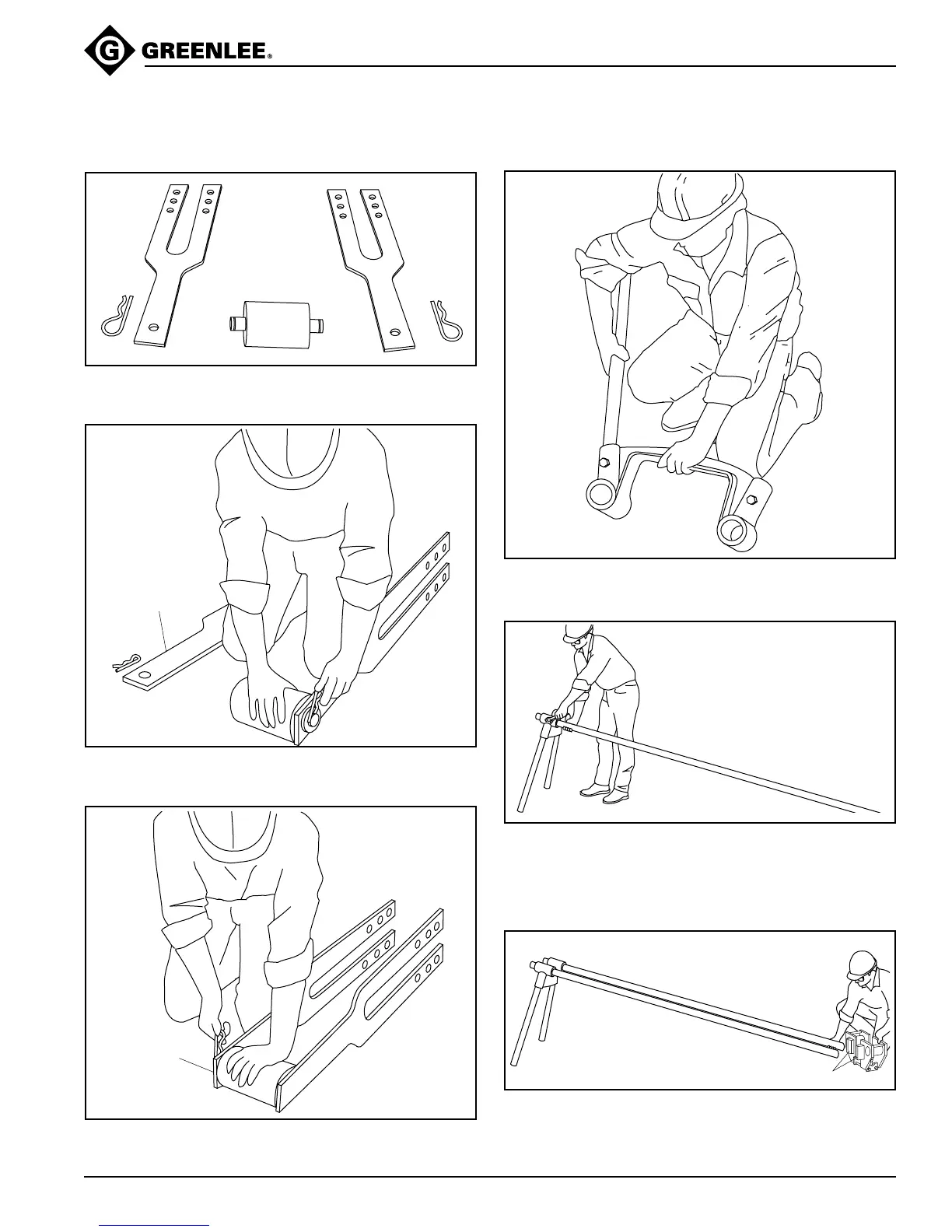
1. Lay out the connecting bars (C), roller unit (D), and
two hitch pin clips (E).
3. Repeat Step 2 for the other connecting bar.
DECALS
FACE OUTWARD
CONNECTING BAR
WITH BENDING
INSTRUCTIONS DECALS
2. Attach the roller unit to one of the connecting bars
with a hitch pin clip, as shown.
5. Insert two 10-foot lengths of IMC or rigid conduit into
the leg support unit (23). Tighten four cap screws (24).
Note: These lengths of conduit are not furnished
with the 1813 Bending Table.
4. Insert 29" leg (25) into leg support unit (23). Tighten
the cap screw (24). Repeat for the other three legs.
6. Position the bender mounting unit (27) as shown,
and slide it, tabs first, onto the two 10-foot conduits.