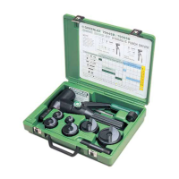
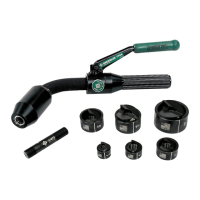
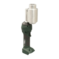
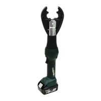
The Greenlee Quick Draw Hydraulic Punch Drivers are self-contained hydraulic tools designed for punching holes of various shapes and sizes through different materials, including mild steel, aluminum, fiberglass, and plastic. When used with Greenlee punches, dies, and draw studs, these drivers form a complete system for efficient hole creation. Slug-Splitter® punches, dies, and studs are also available for punching these materials, as well as stainless steel.
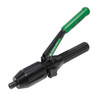
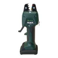
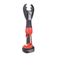
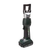
A notable feature of the 7704SB / 7706SB Quick Draw Flex punch driver is its flexible body, which allows for hole punching at a variety of angles. This enhanced flexibility is complemented by handle and release mechanisms that rotate nearly 360 degrees, providing convenient actuation for the user. The other models, the 7804SB / 7806SB Quick Draw and the 7904SB / 7906SB Quick Draw 90, offer robust performance for standard and angled punching tasks, respectively.
Operating these hydraulic punch drivers involves a clear sequence of steps to ensure safety and effectiveness. First, a pilot hole must be drilled in the material. Next, the release valve knob is turned counterclockwise to fully extend the ram. The appropriate die and draw stud components are then assembled and inserted into the pilot hole. It is crucial to thread the punch completely onto the draw stud until it is tight; an incomplete assembly can prevent the hole from being properly completed. Once assembled, the release valve knob is closed, and the lever handle is pumped until the punch has completely passed through the material. Finally, the release valve knob is opened, and the punch is removed.
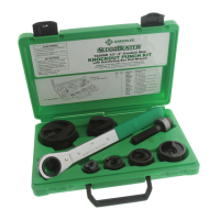
A common technique, "step-up punching," involves using a 1/2" conduit-size punch to enlarge the pilot hole, followed by a 3/4" draw stud to punch the final hole. This method is particularly useful for achieving precise and clean holes. Throughout the operation, it is critical not to operate the pump lever after the ram motion stops, as this can damage the driver and potentially propel internal parts with great force, posing a risk to nearby personnel.
Safety is paramount when using and maintaining Greenlee tools. Users must read and understand all instructions and safety information provided in the manual. Key warnings include avoiding use near live circuits, wearing eye protection to prevent serious injury from flying debris, and inspecting the tool for wear or damage before each use. Any worn, damaged, or missing components should be replaced with genuine Greenlee replacement parts. It is also important not to attempt to punch through two or more layers of material, as this can bend or break the draw stud and forcefully eject parts. The rated capacity of the tool should never be exceeded, as this can lead to component failure. Proper setup is essential, ensuring the punch is fully threaded onto the draw stud and only Greenlee punches, dies, and draw studs are used, as components from other manufacturers may not withstand the generated forces.
Maintenance and repairs should be performed in a dust-free environment by qualified technicians. The Quick Draw drivers require minimal maintenance due to their closed hydraulic system, where all internal parts are lubricated by the hydraulic fluid. Lever pins should be lightly lubricated, and contaminants must be kept away from the ram and cylinder. For storage, the lever should be down, and hydraulic pressure released.
Adding hydraulic oil is a specific maintenance procedure. The driver should be placed in a vise in a vertical position with the handles up. The reservoir handle is unscrewed, and the bladder plug removed. The release valve knob is opened to ensure the ram is fully extended. The rubber bladder is then filled to the point of overflow with Greenlee hydraulic oil. Air must be purged from the system by pumping the lever handle several times with the release valve knob closed until the ram completes its full travel. If air remains, the bladder plug can be removed, and the bladder squeezed while pumping the lever handle with the release valve knob open. After purging, the bladder is refilled to overflow, the bladder plug replaced, and the reservoir handle reassembled.
Regular checks for external oil leaks are necessary, ensuring the release valve knob and stem are tightly closed and seating properly. For the 7904SB / 7906SB models, if the ram section does not rotate, the set screw may need loosening and readjustment. Applying penetrating oil to the cylinder at the attachment point and working the ram section back and forth, followed by SAE 30 oil to the cylinder collar, can resolve this issue. All decals should be kept clean and legible, and replaced when necessary, to ensure all safety information is visible.