
P
Patricia DavisJul 25, 2025
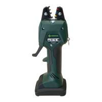
What to do if Greenlee Quick Draw 90 7904SB Power Tool piston will not return and has external oil leaks?
- DDustin KingJul 25, 2025
If your Greenlee Power Tool's piston won't return and you observe external oil leaks, it could be due to a weak or damaged return spring, or too much oil. Refer to the Piston Travel Inspection instructions. Another cause could be damaged seals or surfaces; for this, consult the Cylinder and Pump Block sections within Troubleshooting and Repair. Finally, inspect the Release Valve; see Inspection and Adjustments.