Do you have a question about the Greenlee Quick Draw Series and is the answer not in the manual?
Wear eye protection during operation or servicing to prevent serious eye injury from debris or oil.
Avoid checking oil leaks with hands; pressurized oil can puncture skin, requiring immediate medical attention.
Do not use solvents or flammable liquids to clean the tool body to prevent ignition and injury.
Understand all instructions and safety information before operating or servicing the tool.
Keep hands away from the tool head during punching and remove the battery before changing parts.
Use proper PPE when operating near energized lines as the tool is not insulated.
Ensure no one stands in front of or behind the punch/ram; close access doors on equipment in line.
Inspect tool, punch, die, and drawstud for wear/damage; use only Greenlee replacement parts.
Do not punch through multiple material layers to prevent drawstud bending or component failure.
Do not exceed the tool's rated capacity to prevent component failure and part ejection.
Ensure correct assembly of punch, die, and drawstud for safe operation and to prevent failure.
Use the tool only for its manufacturer-intended purpose to avoid injury or property damage.
Ensure the punch cycle stops after making a hole to prevent part collision.
Support the tool when punching; do not stand beneath an overhead punch as it will fall free.
Do not secure the tool in a vise; it is designed for hand-held operation only.
Do not operate the pump lever after the ram stops to prevent system damage.
Perform only the service and maintenance described in this manual to avoid injury or damage.
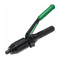
Diagram showing key components: Pump lever, Release valve knob, and Ram.
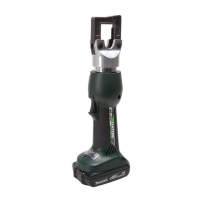
Details on length, width, and mass/weight for the Quick Draw Flex model.
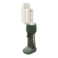
Details on length, width, and mass/weight for the standard Quick Draw model.
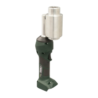
Details on overall length and mass/weight for the Quick Draw 90 model.
Defines operating temperature range and position restrictions.
Step-by-step guide for setting up and performing a punch operation.
Ensures all punch threads are engaged with drawstud threads for proper assembly.
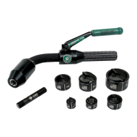
Specific instructions for assembling SPEED PUNCH components with SPEED LOCK.
Details on releasing the punch, removing the die, and clearing slugs.
Inspect tool and components for wear/damage; replace worn or dull parts with Greenlee parts.
Warning regarding non-insulated tool use near energized lines; emphasizes PPE.
Reminder to wear eye protection to prevent injury from flying debris or hydraulic oil.
Instruction to keep hands clear of the tool head during punching operations.
Prohibits securing the tool in a vise, reiterating its hand-held design.
Maximum driver ratings for Slug-Splitter punches in stainless steel by pipe size.
Maximum driver ratings for Standard/Slug-Buster punches in mild steel by pipe size.
Note advising consultation of hydraulic punch manual for punch, drawstud, and die selection.
Inspect for cracks, chips, leaks, and ensure the head rotates freely.
Clean housing with a damp cloth, dry, return ram, and store in a cool, dry place.
Warning against using solvents or flammable liquids to clean the tool body.
Keep hands away from the tool head when punching during maintenance.
Important note that relief valve adjustments require an authorized service center.
Possible cause: Dirt/contaminants. Probable remedy: Clean tool.
Possible cause: Damaged internal seal. Probable remedy: Return to service center.
Possible cause: Pressure valve closed. Probable remedy: Open pressure valve.
Possible cause: Over-tightened. Probable remedy: Bottom tool out and use hex key.
| Model | Quick Draw Series |
|---|---|
| Power Source | Hydraulic |
| Type | Hydraulic Punching Tool |
| Capacity | Up to 1-1/4" (32 mm) |
| Punching Capacity | Up to 1-1/4" (32 mm) |