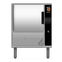
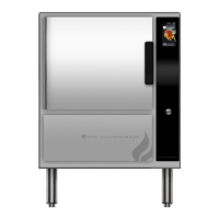
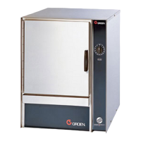
3 OM-GSSP-BL-E BOILERLESS STEAMER
2. Control Panel Removal: While right side panel is removed, carefully disconnect
harness from touchscreen display and on/off switch. Remove screws from
behind front panel and pull control panel away.
3. Supply Voltage: The unit must be operated at the rated name plate voltage. The
name plate can be found inside of the electrical compartment and outside of
the right access panel.
4. Phase Selection: Refer to steamer wiring diagram and element wiring located
on the inside of the right-side access panel.
5. Terminal Block: The terminal block for incoming power is located at the back
of the control compartment. The ground terminal is located in the wiring
compartment near the terminal block.
6. Supply Wire: The equipment grounding wire must comply with the National
Electrical Code (NEC) requirements. The wiring diagram on the inside of the
unit’s right side cover gives directions for proper connection of the terminal
block jumpers. The wire must be used or the unit will not meet Underwriters
Laboratories and NEC requirements. The electric hole is sized for a 3/4 inch (3
and 5-pan) or a 1 inch (10-pan) conduit tting.
7. Branch Circuit Protection: Each Boilerless Steamer, including individual units of
stacked models, should have its own branch circuit protection and ground wire.
8. On/Off Switch (in the rear): There is main power disconnect on the unit. It is
located on rear back panel above the entry hole for incoming electrical supply
wiring.
9. Current and power demands for steamer cavity are as below.
GSSP-BL Steamer
(KW Rating)
RATED CURRENT DEMAND PER CAVITY
208 3P 208 1P 240 3P 240 1P 480 3P
GSSP-BL-3E/ES (9) 25 44 22 38 11
GSSP-BL-5E/ES (12) 34 58 29 50 15
GSSP-BL-10ES (21) 59 N/A 51 N/A 26
WATER CONNECTION(S)
Install a check valve to prevent back ow in the incoming cold water line, as
required by local plumbing codes. Water pressure in the line should be between 30
and 60 PSI. If pressure is above 60 PSI, a pressure regulator will be needed. These
pressures must provide the 1.5 gallons per minute required for proper steamer
function.
Dual water connection: A 3/4 inch female NH connector (garden hose type) is
used to attach the water supply to the inlet valve. Minimum inside diameter of the
water feed line is 1/2 inch. Use a washer in the hose connection. Do not allow the
connection to leak, no matter how slowly. Do not over-tighten hose connections.
This equipment is to be installed to comply with the basic plumbing code of the
Building Ofcials and Code Administrators International, Inc. (BOCA) and the Food
Service Sanitation Manual of the Food and Drug Administration (FDA).
NOTE: Local code may also require check valves in the water supply line.
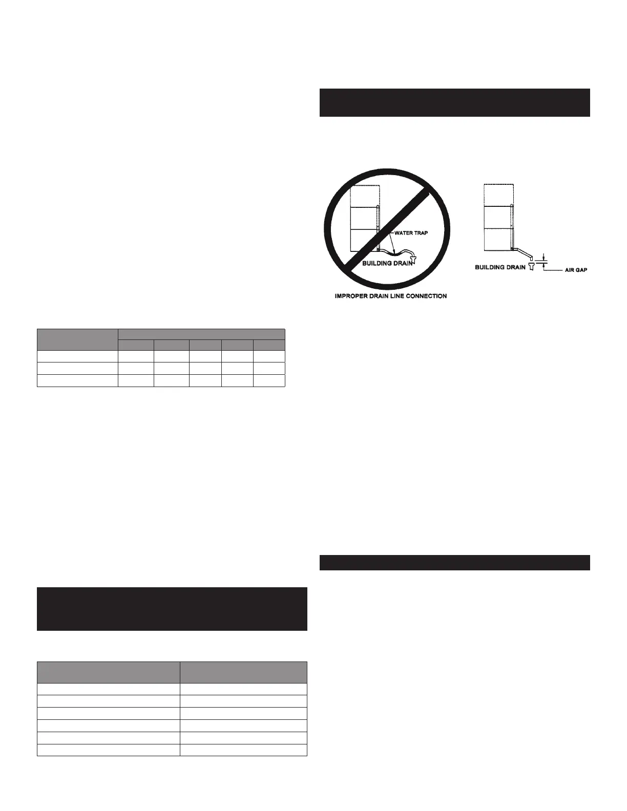
DRAIN CONNECTION
WARNING: DO NOT CONNECT THE DRAIN DIRECTLY TO A BUILDING DRAIN. BLOCKING
THE DRAIN IS HAZARDOUS.
CAUTION: DO NOT USE PLASTIC PIPE. DRAIN MUST BE RATED FOR BOILING WATER.
Level the steamer front to back, and pitch it slightly to the rear (maximum 1/4 inch)
by adjusting the optional legs or the bullet feet on the optional stand.
STEAMER
Drain ID Hose Size
Required (IN)
GSSP-BL-3E/ES 1.5
(2)GSSP-BL-3ES 2.5
GSSP-BL-5E/ES 1.5
(2)GSSP-BL-5E 2.5
GSSP-BL-10ES 2
(2)GSSP-BL-10ES 2.5
There must be a free air gap between the end of the hose and the building drain.
The free air gap should be as close as possible to the unit drain. There must also be
no other elbows or restrictions between the unit drain and the free air gap.
Install the drain line with a constant downward pitch.
IMPORTANT
: DO NOT ALLOW WATER TRAPS IN THE LINE. A TRAP CAN CAUSE PRESSURE
IN THE CAVITY, WHICH MAY CAUSE THE DOOR GASKET TO LEAK.
Proper Drain Line Connection –– Drain Line must have a constant downward pitch
of at least 1/4 per foot. Observe local code regarding air gap spacing and drain
connections.
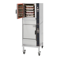
FACTORY-STACKED UNITS
This section is applicable only if you are installing factory-stacked units. Installing
stacked steamers is similar to installing a single unit. The steamers are stacked
and assembled at the factory and delivered with the water connections and drain
hoses required for a single point connection.
1. Dual Water Connections
The same water supply connection is used for both units. At the water inlet
valve a 3/4 inch female NH connector (garden hose type) is used for the water
supply.
2. Electrical Supply Connection
Separate electrical connections will be required for each steamer to be
stacked. Each steamer unit must have it’s own branch circuit protection.
3. Drain Connection
Steamers must be leveled front to back, and pitched to the front (maximum
1/4 inch) by adjusting the bullet feet on the cabinet or stand base.
For all factory-stacked GSSP-BL steamers, a 2-1/2 inch ID hose is attached to
the unit drain. It must be rated for boiling water.
COUNTER-MOUNTED UNITS
WARNING: DO NOT STACK GSSP-BL STEAMERS WHEN LEGS ARE USED.
This section is applicable if the steamer will be mounted to a counter. All four edges
of the bottom of the steamer must be sealed with RTV to the counter if the 4 inch
legs are not used. Counter must be made of a noncombustible material such as
metal or tile.
 Loading...