PART NUMBER 145702, REV. C (01/07)
CALL 888-994-7636 FOR TECHNICAL SUPPORT
12
INSTALLING, CLEANING AND TESTING
Water Connections(s)
No water connection is needed. The water will be poured directly
into the water cavity reservoir.
Make sure that the incoming water connection is made with a 3/4”
N.H. COLD water supply hose. Rigid pipe is not required. The
water pressure should be between 30 and 60 PSIG. Higher
pressures will require the use of a pressure regulator. Make sure
that all connections are tight with no leaks-no matter how small.
NOTICE: The quality of the water is a factor in the proper
performance of the steamer. The water supply should have a
minimum value of 30-40 parts per million of total dissolved solid
(TDS).
Drain Connection
The Vortex100 Connectionless Steamer should be manually
drained to the bottom containment pan supplied by the factory.
If the unit is connected to a drain, do not connect more than
two units to one drain line or pressure from one unit will effect
the second unit.
Steam Vent Assembly Instructions
Remove steam diverter assembly from literature bag which can
be found inside unit. Slide loose end as shown over unit steam
outlet, tighten worm gear clamp with flat head screw driver.
Be sure steam outlet is pointing in the upward position.
(Shown below)
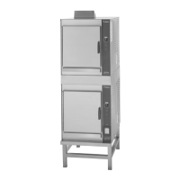
Stacking Units Instructions
Remove drain containment pan from the bottom of unit(s).
Unscrew to remove adjustable legs from base of Vortex unit(s).
Unfasten nuts and bolts on stand platform(s). Place Vortex
unit(s) on stand platform. Align the (4) leg holes with the holes
in the platform. Secure Vortex units(s) to stand platform(s) using
bolts and washers provided with stand, see drawing below.
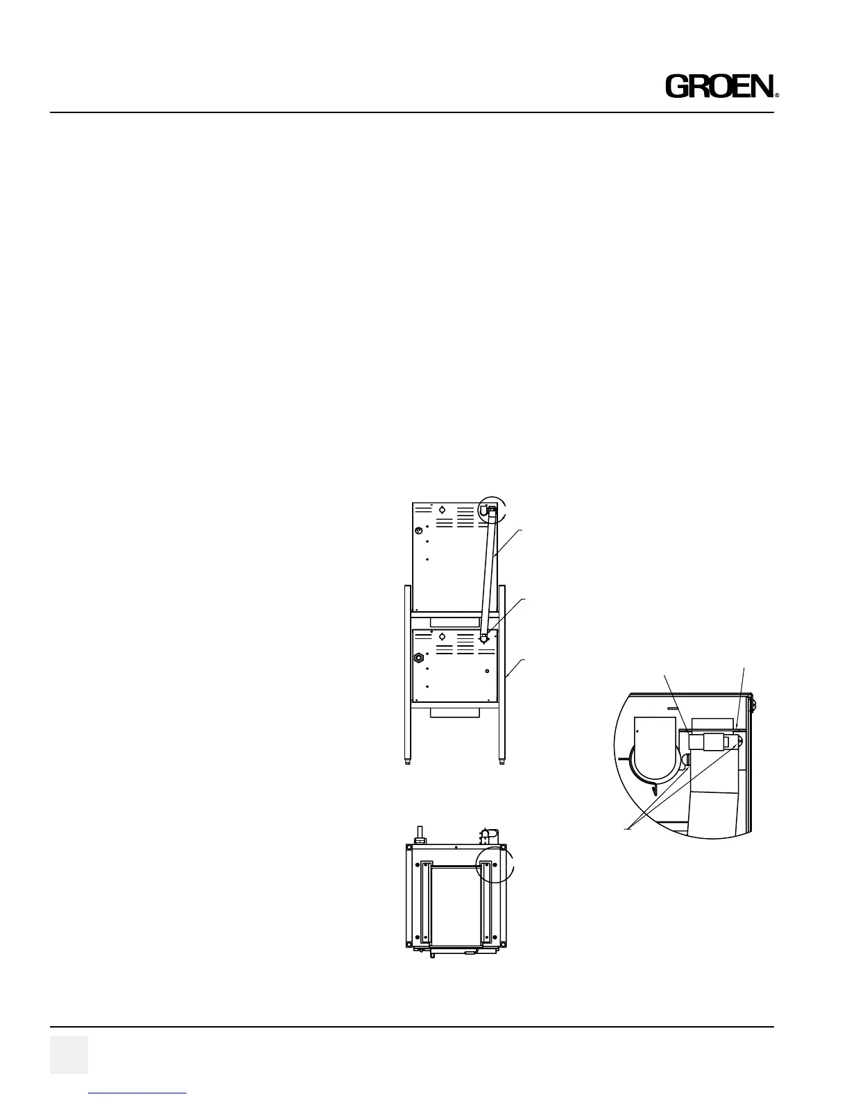
For double stack units only:
By loosening the left screw and removing the right screw provided,
mount steam exhaust bracket assembly to the back panel of the
top Vortex100 unit as shown in detail “B” of Figure 1 on the next
page. Attach the steam exhaust hose from the bottom Vortex
unit’s steam outlet tube to the top Vortex unit’s steam exhaust
bracket assembly using hose clamps provided as shown in figure
2 on the next page. (Note: Steam exhaust hose may need to be
cut to fit.)
FIGURE 1
FIGURE 2
DETAIL B
SCALE 1 : 1
DOUBLE
STACK
STAND P/N
142363
HOSE
CLAMPS
P/N 073259
HOSE
CLAMPS
P/N 073259
DOUBLE STACK
STEAM
EXHAUST HOSE
DOUBLE STACK
STEAM EXHAUST
BRACKET
ASSEMBLY
P/N 143243
10-32 SCREW
P/N 004173
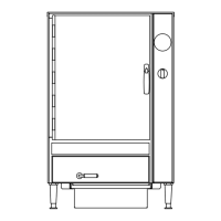
• Units with Manual Fill
• Units with Auto-Fill
Drain Line Installation
Units with auto-fill or manual with drain kit
The drain line should not be less than:
1-1/2” - for single units
2” (5E) - for double stacked units
There must be a 2” air gap to the (non-pressurized) building
drain. Make sure that the drain is sloped AWAY and DOWN
from the steamer and that there are no obstruction in the line.
Failure to observe these requirements may cause a water trap
in the drain line and produce enough back pressure to prevent
proper cavity draining-resulting in condensate water leaking
from the door. Drain line must not NOT be made of plastic pipe.
It must be able to withstand boiling water.