5
Call 1-800/676-9040 for Technical Support
5
ASSEMBLY / DISASSEMBLY
Installation
7. Attach the pipe extension to the drain valve.
8. Attach the drain valve to the pipe nipple attached to the
cavity.
9. Attach the connection bracket to the drain valve body, using
the 1/4” hex nut.
10. Attach the drain actuator shaft to the connection bracket,
using the 3/8” hex nut.
11. Fill the steamer water reservoir with water and check for
leaks.
12. Re-connect the steamer to the branch circuit power supply.
13. Turn on the steamer and check for proper operation.
5.11 Fan - P/N 096790
Removal
1. Turn the steamer off and disconnected from the branch
circuit power, and open the door to allow it to cool before
proceeding.
2. Remove the support rack from in front of the fan.
3. With a 1/8” Allen wrench, loosen the setscrew that holds
the fan to the motor shaft.
4. Hold the fan and with a slight rocking motion, pull the fan
off the motor shaft.
Installation
5. Position the fan hub on the motor shaft so that the 1/8”
Allen set screw is over the flat on the motor shaft.
6. Slide the fan onto the motor shaft so that the motor shaft is
flush with the fan hub.
7. With a 1/8” Allen wrench, tighten the setscrew on the fan.
8. Install the support rack and check for any interference
between the fan and the support rack.
5.12 Heater Element
P/N 142499 208 Volts 12 KW VRC-6E
P/N 142355 240 Volts 12 KW VRC-6E
P/N 142500 480 Volts 12 KW VRC-6E
P/N 150458 208 Volts 10 KW VRC-6E
P/N 150459 240 Volts 10 KW VRC-6E
P/N 160348 480 Volts 10 KW VRC-6E
P/N 142355 208 Volts 9 KW VRC-6E
P/N 142500 240 Volts 9 KW VRC-6E
P/N 141075 208 Volts 9 KW VRC-3E
P/N 141079 240 Volts 9 KW VRC-3E
P/N 141080 480 Volts 9 KW VRC-3E
P/N 141079 208 Volts 6.76 KW VRC-3E
Removal
1. Remove all power connections, drains lines, and fill lines
(if applicable). A stacked unit must be removed from its
location (top or bottom) in order to change the element.
2. Disconnect the element wires connected to the terminal
block.
3. Due to the location of the element and the limited space
available, you must turn the unit upside down.
4. Remove the two side panels.
5. Remove the base of the unit. The base is held in 4 places
attached to the legs.
6. Remove drain lever. This can be done by removing the nut
on the coupling at the valve.
7. Remove the plate support.
8. Remove all the insulation and holding brackets.
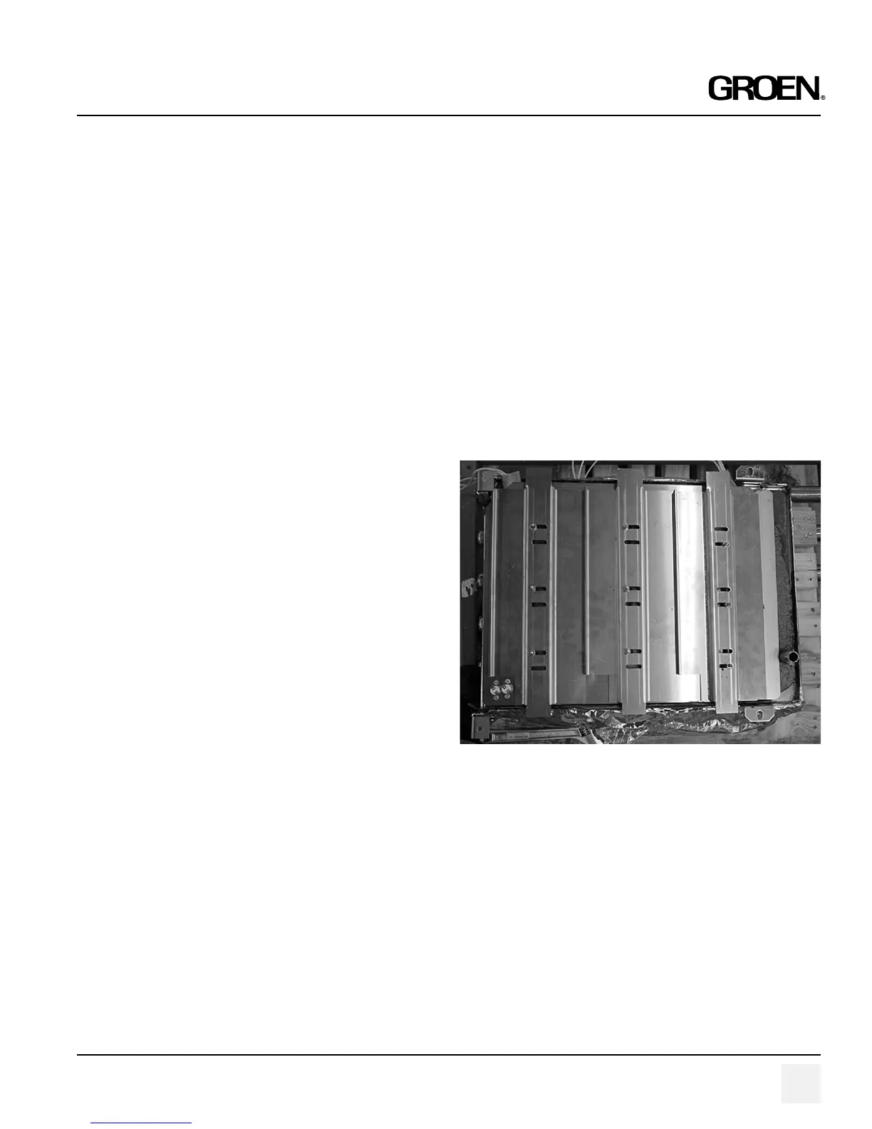
9. Remove the press plate and the lower heat sink plate.
10. Remove element and the upper heat sink plate.
11. Once the upper plate is removed, scrape away ALL the
Thermal Paste material from the bottom of the cavity. In
order to do this effectively, use a putty knife.
PART NUMBER 145702, REV. B (7/06)
9. Turn the branch circuit power on, and turn the steamer on.