Do you have a question about the Groen VRC-3E and is the answer not in the manual?
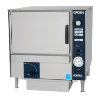
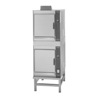
Information for Vortex100 Connectionless Steamer models VRC-3E and VRC-6E.
Groen's history and philosophy in designing and manufacturing commercial appliances.
Details on Groen's certification for equipment inspection, parts availability, and manual updates.
Information regarding warranty provisions and non-warranty related repair procedures.
Overview of safety considerations and signal words used in the manual.
Definitions of abbreviations and terms used in the service manual.
Lists required and recommended tools, instruments, and supplies for inspection and repair.
Guidance on how to effectively use the service manual for repairs.
Description of operator controls, touch pads, and indicator lights on the unit.
Step-by-step guide for operating the Vortex100 Connectionless Steamer.
Instructions for unit installation, including electrical supply connection and branch circuit protection.
Checklist for ensuring proper installation and initial setup of the steamer.
Procedures for cleaning the VRC-3E or VRC-6E Connectionless Steamer.
A systematic procedure for diagnosing and resolving issues with the Vortex100 steamer.
Procedure for checking the operation of the VRC unit through diagnostics and functional tests.
Procedures for removing and installing the air temperature probe.
Steps for removing and installing the cavity vent assembly (pressure relief valve).
Procedures for removing and installing the control PC board.
Steps for removing and installing the relay board.
Detailed instructions for removing, installing, and aligning the steamer door.
Procedures for removing and installing the door switch.
Step-by-step guide for reversing the steamer door.
Instructions for removing and installing the door gasket.
Procedures for removing and installing the door spring assembly.
Steps for removing and installing the door locking pin and nut.
Procedures for removing and installing the drain valve assembly.
Steps for removing and installing the fan.
Procedures for removing and installing the heater element.
Steps for removing and installing the hi-limit thermostat.
Procedures for removing and installing the leg assemblies.
Steps for removing and installing the fan motor assembly.
Procedures for removing and installing the motor starting capacitor.
Steps for removing and installing the back panel.
Procedures for removing and installing the right and left side panels.
Steps for removing and installing the top panel.
Procedures for removing and installing the remote reading thermometer.
Steps for removing and installing the water level float.
Instructions for installing the water drain kit.
Detailed parts list and diagram for the cavity vent assembly.
Parts list and diagram for the control board and associated wiring harnesses.
Parts list and diagram for the door assembly.
List and diagram of electrical components for 208, 240, and 480 volt models.
Parts list and diagram for the heater element assembly.
Parts list and diagram for the motor assembly.
Parts list and diagram for float assemblies.
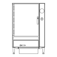
Parts list and diagram for interior and exterior cabinet components.
Detailed parts list and diagram for the cavity vent assembly.
Parts list and diagram for the control board and associated wiring harnesses.
Parts list and diagram for the door assembly.
List and diagram of electrical components for 208, 240, and 480 volt models.
Parts list and diagram for the heater element assembly.
Parts list and diagram for the motor assembly.
Parts list and diagram for float assemblies.
Parts list and diagram for interior and exterior cabinet components.
Overview of general specifications for the Vortex100 Connectionless Steamer.
Details on electrical requirements, voltage, phase, and amperage for VRC-3E and VRC-6E.
Schematic illustrating the wiring connections for VRC-3E and VRC-6E models.
Ladder diagram showing control logic and component interconnections.
| Drain | Yes |
|---|---|
| Voltage | 220-240 V |
| Frequency | 60 Hz |
| Water Inlet | Automatic water fill |
| Material | Stainless Steel |
| Description | Electric Steamer |