EasyManua.ls Logo

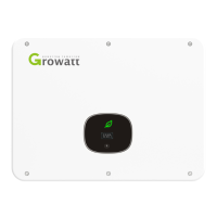
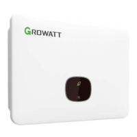
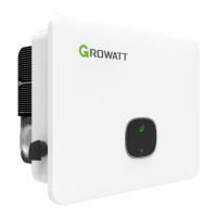
Growatt MID TL3-XH Series - User Manual

Growatt MID TL3-XH Series
63 pages
Print Icon
To Next Page IconTo Next Page
Loading...
Download
Manual
Growatt New Energy
Installation
&
Operation Manual
GR-UM-320-A-00
Shenzhen Growatt New Energy Co., Ltd
4-13/F, Building A, Sino-German (Europe) Industrial Park,
Hangcheng Ave, Bao’an District, Shenzhen, China
+86 755 2747 1942
www.ginverter.com
T
E
W
service@ginverter.com

Questions and Answers

  • O
    ocruzSep 4, 2025
    How do I troubleshoot Warning 400 on my Growatt MID TL3-XH Inverter?
    • M
      Misty MillerSep 4, 2025
      If your Growatt Inverter is displaying Warning 400, after shutdown, check the connection of the fan and replace the fan. If the error message persists, please contact Growatt support.
  • A
    Andrea WangAug 25, 2025
    What to do if my Growatt MID TL3-XH Inverter displays Error 309?
    • D
      danielhallAug 25, 2025
      If your Growatt Inverter shows Error 309, check the grid frequency and restart the inverter. If the error message persists, please contact Growatt support.
  • D
    Darren HowardAug 25, 2025
    What should I do if my Growatt MID TL3-XH Inverter is showing Error 301?
    • B
      Breanna Sims DVMAug 26, 2025
      If your Growatt Inverter displays Error 301, check the AC terminals. If the error message continues, contact Growatt support for further assistance.
  • D
    Dillon PerezSep 12, 2025
    How to fix Warning 306 on a Growatt MID TL3-XH Inverter?
    • J
      janetbaldwinSep 12, 2025
      To address Warning 306 on your Growatt Inverter, check the connection of the communication cable. If the error message persists, please contact Growatt support.
  • R
    Russell JacksonSep 18, 2025
    What should I do if my Growatt MID TL3-XH displays Warning 605?
    • L
      lindaparkerSep 18, 2025
      If your Growatt Inverter displays Warning 605, try restarting the inverter. If the error message persists, please contact Growatt support.
  • J
    James WeaverSep 7, 2025
    How to fix Warning 204 on a Growatt Inverter?
    • T
      Thomas HaasSep 7, 2025
      If your Growatt Inverter is showing Warning 204, after shutdown, check the dry contact wiring. If the error message persists, please contact Growatt support.
  • Z
    zachary40Aug 31, 2025
    What should I do if I see Warning 423 on my Growatt MID TL3-XH Inverter?
    • M
      michaelandersonAug 31, 2025
      If your Growatt Inverter displays Warning 423, restart the inverter. If the error message persists, please contact Growatt support.
  • T
    Tyler NelsonSep 23, 2025
    How to fix Error 204 on a Growatt Inverter?
    • R
      Richard KellySep 23, 2025
      If your Growatt Inverter is showing Error 204, after shutdown, check the connection of the PV terminals and restart the inverter. If the error message persists, please contact Growatt support.
  • A
    Angela HernandezSep 14, 2025
    What should I do if my Growatt MID TL3-XH Inverter displays Warning 502?
    • J
      Joseph HouseSep 14, 2025
      If your Growatt Inverter shows Warning 502, check whether the grid voltage is out of range or whether the grid-connected voltage setting of the inverter is correct. Check whether the PV voltage is too high or too low. Restart the inverter. If the error message persists, please contact Growatt support.
  • D
    Daniel GrossAug 28, 2025
    What to do if my Growatt MID TL3-XH Inverter is showing Warning 219?
    • A
      Ashley KingAug 28, 2025
      If your Growatt Inverter displays Warning 219, restart the inverter. If the error message persists, please contact Growatt support.

Summary

Notes on this manual

1.1 Validity

Specifies the validity of the manual and lists supported device types.

1.2 Intended audience

Identifies the target audience and provides contact information for support.

1.3 Symbols in this document

Explains warning symbols, safety labels, and provides a glossary of terms.

Safety

2.1 Product description and features

Details the inverter's design, MPP trackers, and key product features.

2.3 Safety instructions

Provides comprehensive safety guidelines for installation, operation, and maintenance.

Product overview

3.1 Appearance

Describes the physical components of the inverter and its status indicators.

3.2 Dimensions

Presents the physical dimensions and weight specifications of the inverter models.

Inspection upon delivery

4.1 Scope of Delivery

Lists the components included in the inverter package and instructions for checking completeness.

Installation

5.1 Basic installation requirements

Outlines essential requirements for inverter installation, including location and environmental conditions.

5.2 Wall-mounted installation

Details the procedure for installing the wall-mounting bracket and the inverter.

Electrical connection

6.1 Precautions

Highlights critical safety precautions before and during electrical connections.

6.2 AC side wiring

Provides step-by-step instructions and warnings for connecting the AC power.

6.3 DC side wiring

Details the DC input wiring procedures and associated safety warnings.

6.4 Connecting the Bidirectional DC;DC Box

Explains conditions and steps for connecting a bidirectional DC/DC box.

6.5 Connecting the signal cable

Describes how to connect and disconnect the signal cable for communication.

6.6 Grounding the inverter

Explains the importance and method of grounding the inverter for safety.

6.7 Active power control with a smart meter or a ripple control receiver

Details how to use external devices for active power control and export limitation.

6.8 Demand response modes (DRMs)

Explains Demand Response Modes and their application via a 16-pin socket.

6.9 GFCI (Standard)

Covers Ground Fault Circuit Interrupter functionality and installation advice.

6.10 AFCI (Optional)

Details the Arc-Fault Circuit Interrupter function, safety, and operation steps.

6.11 Backup function (Optional)

Explains how to enable and configure the inverter's backup mode with a battery.

Commissioning

7.1 Commissioning Steps

Provides the sequence of steps for commissioning the inverter after installation.

Working mode

8.1 Operating mode

Describes the normal operating state of the inverter when connected to the grid.

8.2 Failure mode

Explains the inverter's behavior and indicators during a system or inverter failure.

OLED display and the touch button

9.1 Starting the inverter

Guides on starting the inverter and using the touch button for interface navigation.

9.2 General settings

Details how to configure general settings like display language, date, and time.

9.3 Advanced settings

Explains how to access and configure advanced settings, including export limitation and backup mode.

Communication and monitoring

10.1 COM port

Describes the COM port functions, pin assignments, and connection for monitoring.

10.2 USB-A port

Explains the usage of the USB-A port for connecting monitoring modules and firmware updates.

Maintenance and cleaning

11.1 Checking the heat dissipation

Recommends cleaning the heat sink to improve heat dissipation and prevent performance reduction.

11.2 Checking the inverter

Provides instructions for cleaning the inverter's enclosure, display, and indicators.

Powering on;off the inverter

12.1 Powering on the inverter

Outlines the correct sequence of steps for safely powering on the inverter.

12.2 Powering off the inverter

Details the procedure for safely powering off the inverter and its components.

Troubleshooting

13.1 Error message

Lists information required to provide technical assistance for error messages.

13.2 System warning

Provides a table of system warnings, their descriptions, and troubleshooting steps.

13.3 System error

Lists system error codes, their descriptions, and recommended troubleshooting actions.

Decommissioning

15.1 Removing the inverter

Step-by-step guide on how to safely remove the inverter from its mounting.

15.4 Disposing of the Inverter

Provides guidelines for the environmentally responsible disposal of the inverter.

Contact us

19.1 Technical Support Information

Lists essential information required for contacting technical support for product issues.

Growatt MID TL3-XH Series Specifications

General IconGeneral
Number of MPPTs2
Number of DC Inputs per MPPT2
Nominal Grid Frequency50 Hz / 60 Hz
THDi< 3%
DC SwitchYes
TopologyTransformerless
Nominal AC Voltage230V
AC Voltage Range180V - 280V
Operating Temperature Range-25°C to 60°C
CommunicationWiFi/GPRS (Optional)

Related product manuals