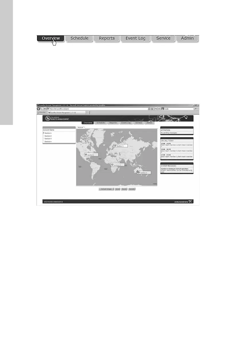
EasyManuals Logo

Grundfos CIU 501 User Manual

Grundfos CIU 501
64 pages
To Next Page IconTo Next Page
To Previous Page IconTo Previous Page
Page #10 background imageLoading...
Page #10 background image
English (GB)
10
DIP switch settings
Software-defined parity and stop bits
When SW4 and SW5 are set to "software-defined", the value in
the holding registers at addresses 00009 and 00010 will override
the setting of SW3. See figs 14 and 15.
The software-defined parity and stop bit values are stored in the
communication interface and remain after a power-off.
5.3 Modbus address selection
A Modbus slave on a Modbus network must have a unique
address from 1-247. Address 0 is reserved for broadcasting and
is not a valid slave address.
To set the Modbus address, use two hexadecimal rotary switches,
SW6 and SW7. See fig. 16.
Fig. 16 Setting the Modbus address
For a complete overview of Modbus addresses, see section
14. Fault finding the product.
5.4 Termination resistor
The termination resistor is fitted on CIM 200 Modbus and has a
value of 150 Ω.
CIM 200 has two DIP switches, SW1 and SW2, for cutting the
termination resistor in and out. Fig. 17 shows the DIP switches in
cut-out state.
Fig. 17 Cutting the termination resistor in and out
DIP switch settings
Default setting: Termination resistor cut out.
Cable length
We recommend the following maximum lengths:
5.5 Status LEDs
CIM 200 Modbus has two status LEDs: LED1 and LED2. See
fig. 13.
Red and green status LED1 for Modbus communication
Red and green status LED2 for internal communication
between CIM 200 and the Grundfos product.
LED1
LED2
Parity SW3
Even parity, 1 stop bit OFF
No parity, 2 stop bits ON
Software-defined parity
Value to set in register
00009
No parity [default] 0
Even parity 1
Odd parity 2
Software-defined stop bit
Value to set in register
00010
1 stop bit [default] 1
2 stop bits 2
For software-defined parity and stop bits to become
active, you must set SW4 and SW5 to ON.
TM04 1706 0908
When software-defined transmission speed is
enabled, software-defined address is also enabled
and you set the address via register 00003.
You must set the Modbus address decimally from 1
to 247.
TM04 1701 0908
Status SW1 SW2
Cut in ON ON
Cut out
OFF OFF
ON OFF
OFF ON
Bits/s
Maximum cable length
Terminated cable Unterminated cable
[m/ft] [m/ft]
1200-9600 1200/4000 1200/4000
19200 1200/4000 500/1700
38400 1200/4000 250/800
To ensure stable and reliable communication, it is
important that only the termination resistor of the first
and last units in the Modbus network are cut in.
All switch settings will be effective immediately after
setting the values. No power-off is needed.
Status Description
Off No Modbus communication.
Flashing green Modbus communication active.
Flashing red Fault in the Modbus communication.
Permanently red
Fault in the CIM 200 Modbus
configuration.
Status Description
Off CIM 200 has been switched off.
Flashing red
No internal communication between CIM
200 and the Grundfos product.
Permanently red
CIM 200 does not support the Grundfos
product connected.
Permanently green
Internal communication between CIM 200
and the Grundfos product is OK.
During startup, there is a delay of up to 5 seconds
before LED2 status is updated.

Table of Contents

Other manuals for Grundfos CIU 501

Questions and Answers:

Question and Answer IconNeed help?

Do you have a question about the Grundfos CIU 501 and is the answer not in the manual?

Grundfos CIU 501 Specifications

General IconGeneral
BrandGrundfos
ModelCIU 501
CategoryController
LanguageEnglish

Related product manuals