English (GB)
6
5. Logging on
To log on to the GRM server system, go to https://
remotemanagement.grundfos.com.
You will be prompted for user name and password.
Current users of the Grundfos Extranet can log on
with their Extranet user name and password. New
users will receive an e-mail with log-on details.
If you do not have a user name and a password,
contact your local Grundfos company, or send an e-
mail to remote-management@grundfos.com.
When you log on for the first time, a navigation tree
will appear. See fig. 3.
The basic steps in setting up an account are
described in the following section.
5.1 Navigation
To provide an overview of the installations monitored
by the GRM system, a navigation tree is used.
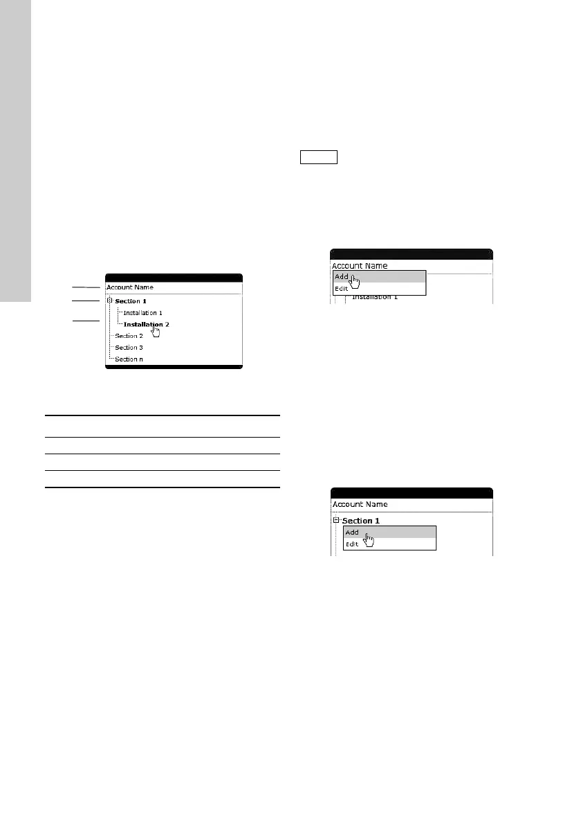
Fig. 3 Navigation tree
The navigation tree is divided into three levels:
5.1.1 Account level
At the account level, you will find the name and
details of your account.
5.1.2 Section level
At the section level, it is possible to create several
sections. Sections are logical groups of one or more
installations.
At the installation level, you will find the devices that
are monitored. An installation is defined by a modem
monitoring one or more bus devices or sensors.
Adding a section
1. Right-click [Account name].
2. Click [Add].
Fig. 4 Adding a section
When you have created the section, you can add an
installation to the section.
5.1.3 Installation level
An installation is always added to a section and
consists of a communication device and a number of
monitored devices, normally a CIM 500 and at least
one GENIbus device (Grundfos pump, pump
controller or I/O module).
Adding an installation
1. Right-click the section name.
2. Click [Add].
Fig. 5 Adding an installation
The setup of an installation is a four-step procedure:
1. Create an installation.
2. Set up the installation.
3. Configure and connect the installation.
4. Configure alarms and warnings.
TM04 7282 2410
Pos. Level
1 Account
2 Section
3 Installation
Sections could, for example, reflect a
geographical segmentation of the entire
monitored network or segmentation
according to area of expertise or
responsibility of a group of persons.
TM04 7283 2410TM04 7284 2410
 Loading...