English (GB)
16
12. Admin, user administration
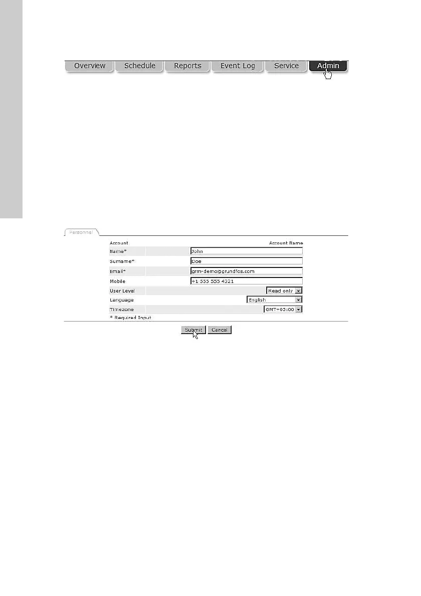
Fig. 23 Admin
Under this tab, you will find the functionality to create
new users and to maintain the data of each
registered user of the system.
To create a new user, fill in the following:
• first name
• second name
• e-mail.
This is the minimum information required to create a
new user in Grundfos Remote Management.
The field "Mobile" is optional. This number will be
used to send SMS alarms to the user, if registered as
an alarm recipient on a schedule.
Fig. 24 Creating a new user
Now select the appropriate user access level. Users
can be assigned different access levels, depending
on their intended use of the system.
There are three different access levels:
• full access
• operator access
• read-only access.
TM04 7304 2410TM04 7305 2410
 Loading...