EasyManuals Logo

Grundfos CIU 501 User Manual

Grundfos CIU 501
64 pages
To Next Page IconTo Next Page
To Previous Page IconTo Previous Page
Page #9 background imageLoading...
Page #9 background image
English (GB)
9
5. CIM 200 Modbus RTU setup
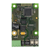
Fig. 13 CIM 200 Modbus module
Use a screened, twisted-pair cable. Connect the cable screen to
protective earth at both ends.
Recommended connection
5.1 Setting the Modbus transmission speed
Set the transmission speed correctly before the CIM 200 Modbus
module is ready to communicate with the Modbus network. Use
DIP switches SW4 and SW5 for setting the transmission speed.
See fig. 14.
Fig. 14 Modbus transmission speed
DIP switch settings
Available transmission speeds in bits/s: 1200, 2400, 4800, 9600,
19200 and 38400.
The first three transmission speeds are only available via
software settings, whereas the last three are available via DIP
switches.
Default transmission speed is 19200 bits per second, as per the
Modbus RTU standard.
Software-defined
When SW4 and SW5 are set to "software-defined", writing a
value to the holding register at address 00004 will set a new
transmission speed.
Use the following values for software-defined transmission
speeds:
This value is set to 1200 bits/s as default.
The communication interface does not support transmission
speeds above 38400 bits/s.
The software-defined transmission speed value is stored in the
communication interface and remains after a power-off.
5.2 Setting the stop bits and the parity bit
You can set the parity either manually by using SW3 or via
software-defined settings.
Manual setting of parity
Default byte format (11 bits):
•1 start bit
8 data bits (least significant bit sent first)
1 parity bit (even parity)
1 stop bit.
The default setting of the CIM 200 Modbus module is even parity
(1 stop bit). It is possible to change the parity using DIP switch
SW3. You can change the parity to no parity (2 stop bits). See
fig. 15.
Fig. 15 Parity
TM04 1697 0908
Pos. Designation Description
1D1
Modbus terminal D1 (positive data
signal)
2D0
Modbus terminal D0 (negative data
signal)
3 Common/GND Modbus terminal Common and GND
4SW1/SW2
On and off switches for termination
resistor
5 SW3/SW4/SW5
Switches for selection of Modbus
parity and transmission speed
6LED1
Red and green status LED for
Modbus communication
7LED2
Red and green status LED for
internal communication between
CIM/CIU 200 and the booster system
8SW6
Hexadecimal rotary switch for setting
the Modbus address, four most
significant bits
9SW7
Hexadecimal rotary switch for setting
the Modbus address, four least
significant bits
Modbus terminal Colour code Data signal
D1-TXD1 Yellow Positive
D0-TXD0 Brown Negative
Common/GND Grey Common/GND
TM04 1710 0908
1 2 34 5 6 7
8
9
Transmission speed [bits/s] SW4 SW5
9600 OFF ON
19200 OFF OFF
38400 ON OFF
Software-defined ON ON
Software-defined transmission
speed
Value to set in register
00004
1200 bits/s 0
2400 bits/s 1
4800 bits/s 2
9600 bits/s 3
19200 bits/s 4
38400 bits/s 5
When software defined has been selected, then
communication speed, parity bit, stop bits and
address are all set via specific registers. See section
5.2 Setting the stop bits and the parity bit and section
5.3 Modbus address selection.
When software-defined transmission speed is
enabled (SW4 and SW5 are ON), software-defined
parity and stop bits are also enabled.
TM04 1709 0908
SW3

Table of Contents

Other manuals for Grundfos CIU 501

Questions and Answers:

Question and Answer IconNeed help?

Do you have a question about the Grundfos CIU 501 and is the answer not in the manual?

Grundfos CIU 501 Specifications

General IconGeneral
BrandGrundfos
ModelCIU 501
CategoryController
LanguageEnglish

Related product manuals