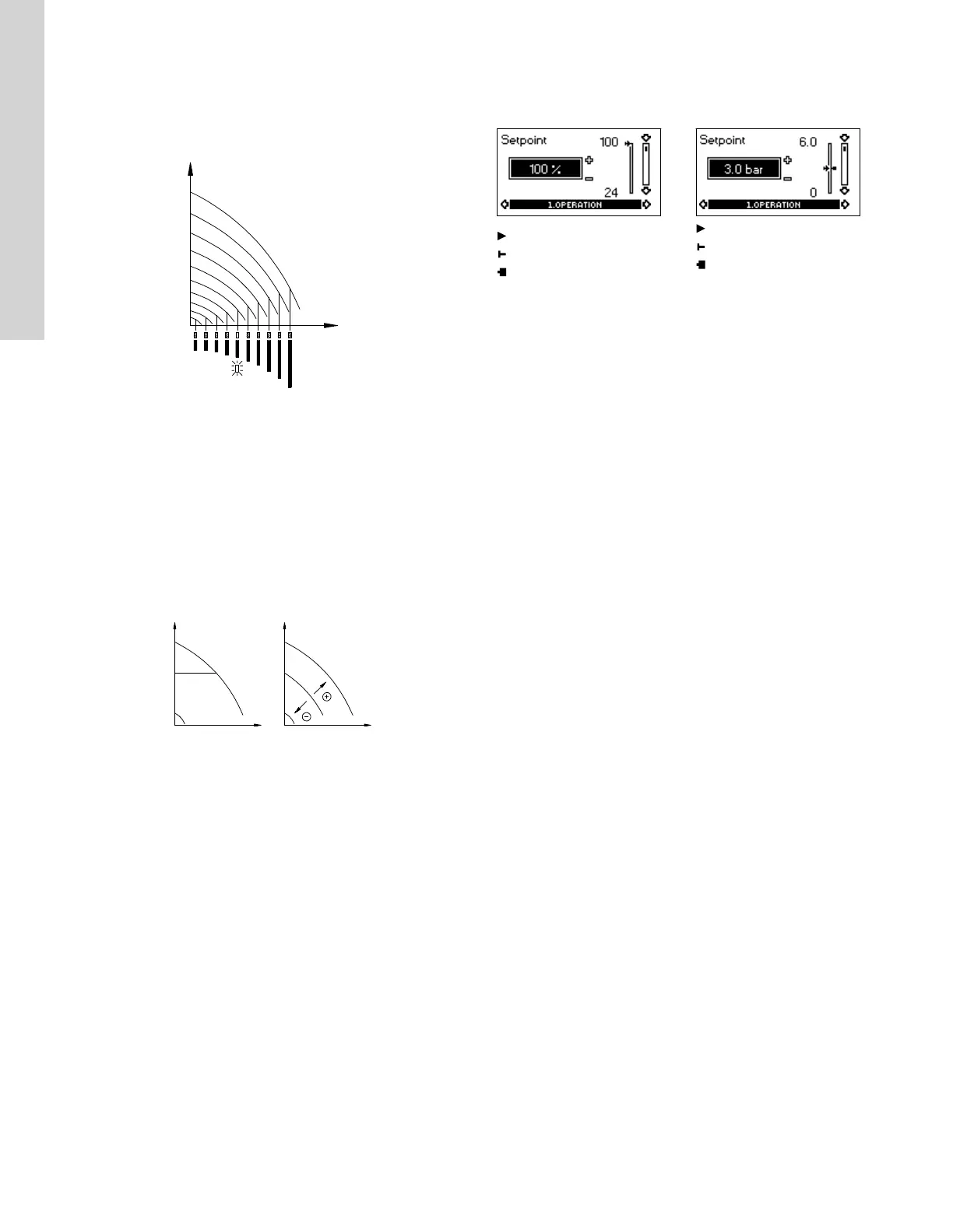
4.7.3 Control mode
Pumps without factory-fitted sensor
The pumps are factory-set to control mode uncontrolled.
In control mode uncontrolled, the pump will operate according to the
constant curve set, see the figure below.
TM007746
Pump in control mode uncontrolled (constant curve)
4.7.4 Pumps with pressure sensor
The pump can be set to one of two control modes, i.e. controlled
and uncontrolled, see the figure below.
In control mode controlled, the pump will adjust its performance, i.e.
pump discharge pressure, to the desired setpoint for the control
parameter.
In control mode uncontrolled, the pump will operate according to the
constant curve set.
Controlled
Uncontrolled
TM007668
Pump in control mode controlled (constant pressure) or
uncontrolled (constant curve)
5. Control functions
5.1 Displays in general
In the following explanation of the functions, one or two displays are
shown.
One display
Pumps without or with factory-fitted sensor have the same function.
Two displays
Pumps without or with factory-fitted pressure sensor have different
functions and factory settings.
5.2
Menu OPERATION
The first display in this menu is this:
5.2.1
Setpoint
Without sensor
(uncontrolled)
With pressure sensor
(controlled)
Setpoint set
Actual setpoint
Actual value
Set the setpoint in %.
Setpoint set
Actual setpoint
Actual value
Set the desired pressure in
bar.
In control mode uncontrolled, the setpoint is set in % of the
maximum performance. The setting range will lie between the min.
and max. curves.
In control mode controlled, the setting range is equal to the sensor
measuring range.
If the pump is connected to an external setpoint signal, the value in
this display will be the maximum value of the external setpoint
signal. See the section on external setpoint signal.
Setpoint and external signal
The setpoint cannot be set if the pump is controlled via external
signals (Stop, Min. curve or Max. curve). R100 will give this
warning: External control!
Check if the pump is stopped via terminals 2-3 (open circuit) or set
to min. or max. via terminals 1-3 (closed circuit).
See fig. 'Menu overview'.
Setpoint and bus communication
The setpoint cannot be set either if the pump is controlled from an
external control system via bus communication. R100 will give this
warning: Bus control!
To override bus communication, disconnect the bus connection.
See fig. 'Menu overview'.
Related information
5.6 Typical display settings for analog-input E-pumps
5.8 External setpoint signal
12
English (US)

 Loading...


