5.3 Menu STATUS
The displays appearing in this menu are status displays only. It is
not possible to change or set values.
The displayed values are the values that applied when the last
communication between the pump and the R100 took place. If a
status value is to be updated, point the R100 at the control panel
and press "OK". If a parameter, e.g. speed, should be called up
continuously, press "OK" constantly during the period in which the
parameter in question should be monitored.
The tolerance of the displayed value is stated under each display.
The tolerances are stated as a guide in % of the maximum values
of the parameters.
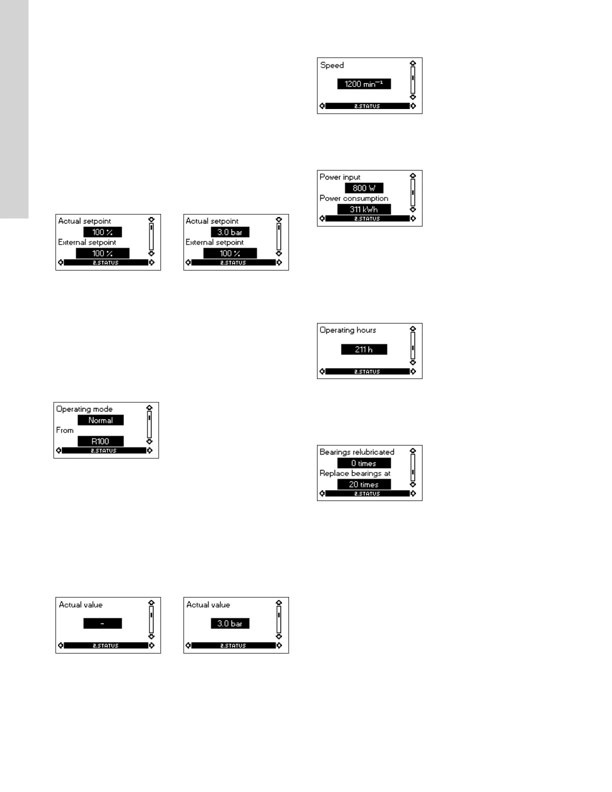
5.3.1 Actual setpoint
Without sensor
(uncontrolled)
With pressure sensor
(controlled)
Tolerance: ± 2 %. Tolerance: ± 2 %.
This display shows the actual setpoint and the external setpoint in
% of the range from minimum value to the setpoint set. See the
section on external setpoint signal.
Related information
5.8 External setpoint signal
5.8 Signal externe du point de consigne
5.8 Señal de punto de ajuste externo
5.3.2
Operating mode
This display shows the actual operating mode (Normal (duty), Stop,
Min., or Max.). Furthermore, it shows where this operating mode
was selected (R100, Pump, Bus, External or Stop func.). For further
details about the stop function (Stop func.), see the section on stop
function.
Related information
5.4.8 Stop function
5.3.3
Actual value
Without sensor
(uncontrolled)
With pressure sensor
(controlled)
This display shows the value actually measured by a connected
sensor.
If no sensor is connected to the pump, "-" will appear in the display.
5.3.4
Speed
Tolerance: ± 5 %
The actual pump speed will appear in this display.
5.3.5 Power input and power consumption
Tolerance: ± 10 %
This display shows the actual pump input power from the power
supply. The power is displayed in W or kW.
The pump power consumption can also be read from this display.
The value of power consumption is an accumulated value
calculated from the pump’s birth and it cannot be reset.
5.3.6 Operating hours
Tolerance: ± 2 %
The value of operating hours is an accumulated value and cannot
be reset.
5.3.7
Lubrication status of motor bearings (only 20-30 hp)
This display shows how many times the motor bearings have been
relubricated and when to replace the motor bearings.
When the motor bearings have been relubricated, confirm this
action in the INSTALLATION menu. See the section on confirming
relubrication/replacement of motor bearings (only three-phase
pumps). When relubrication is confirmed, the figure in the above
display will be increased by one.
Related information
5.4.14 Confirming relubrication/replacement of motor bearings
(only three-phase pumps)
14
English (US)

 Loading...


