Pos. Description
1 Digital input 2
2 Start/stop
3 GND (frame)
4 Setpoint input
5 +10 V
6 GND (frame)
7 Sensor input
8 +24 V
9 GND (frame)
10 Digital input 3
11 Digital input 4
12 Analog output
13 GND
14 Sensor input 2
15 +24 V
16 GND (frame)
17 PT 100 A
18 PT 100 A
19 PT 100 B
20 PT 100 B
G1 Group 1
G2 Group 2
G3 Group 3
A RS-485A
B RS-485B
Y Screen
A galvanic separation must fulfill the requirements for reinforced
insulation including creepage distances and clearances specified in
EN 61800-5-1.
4.4.10
Signal cables
• Use screened cables with a conductor cross-section of min. 28
AWG and max. 16 AWG for external on/off switch, digital input
and setpoint signals.
• Connect the screens of the cables to frame at both ends with
good frame connection. The screens must be as close as
possible to the terminals. See the figure below.
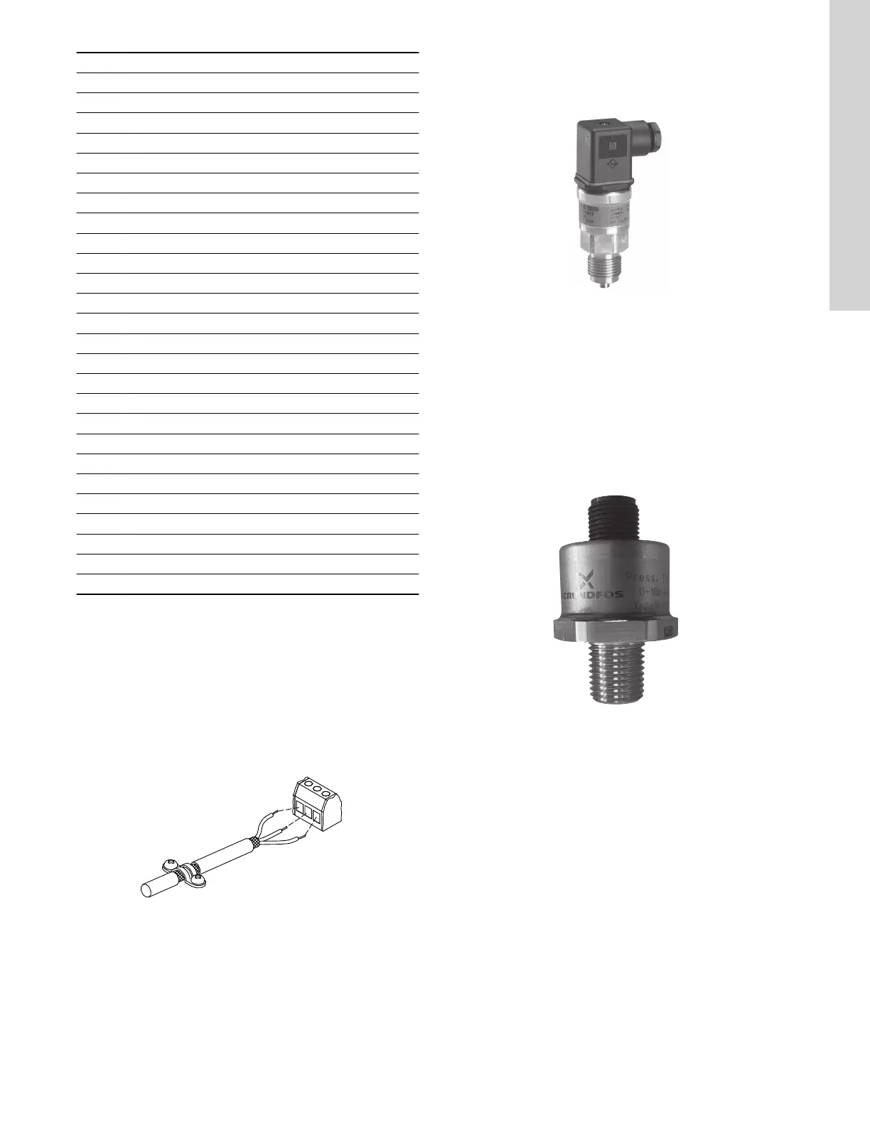
TM021325
Stripped cable with screen and wire connection
• Always tighten screws for frame connections whether a cable is
fitted or not.
• Make the wires in the pump terminal box as short as possible.
4.5
E-pump electrical connections
4.5.1 Connection of Danfoss pressure sensor MBS3000 to E-
pump
TM051533
Danfoss pressure sensor
Use screened cables with a cross-sectional area of minimum 28
AWG and maximum 16 AWG.
The blue wire of the pressure sensor is connected to the #7
terminal of the E-pump. The brown wire of the pressure sensor is
connected to the #8 terminal of the E-pump.
Related information
4.4.10 Signal cables
4.5.2
Connection of Grundfos pressure sensor ISP44 to E-
pump
TM083396
ISP44 pressure sensor
Use unscreened cables with a cross-sectional area of minimum 28
AWG and maximum 16 AWG.
The blue wire of the pressure sensor is connected to the #7
terminal of the E-pump. The brown wire of the pressure sensor is
connected to the #8 terminal of the E-pump.
9
English (US)

 Loading...


