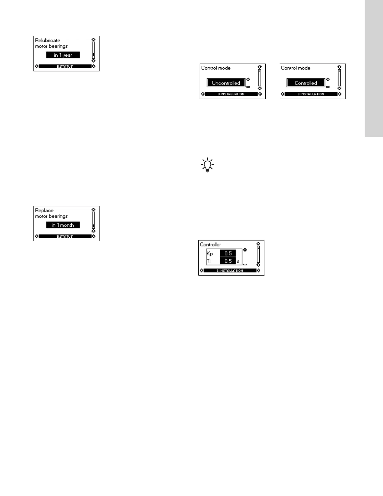
5.3.8 Time till relubrication of motor bearings
This display shows when to relubricate the motor bearings. The
controller monitors the operating pattern of the pump and calculates
the period between bearing relubrications. If the operating pattern
changes, the calculated time till relubrication may change as well.
The displayable values are these:
• in 2 years
• in 1 year
• in 6 months
• in 3 months
• in 1 month
• in 1 week
• Now!
5.3.9 Time till replacement of motor bearings
When the motor bearings have been relubricated a prescribed
number of times stored in the controller, the display in the section
on time till relubrication of motor bearings will be replaced by the
display below.
This display shows when to replace the motor bearings. The
controller monitors the operating pattern of the pump and calculates
the period between bearing replacements.
The displayable values are these:
• in 2 years
• in 1 year
• in 6 months
• in 3 months
• in 1 month
• in 1 week
• Now!
Related information
5.3.8 Time till relubrication of motor bearings
5.4 Menu INSTALLATION
5.4.1 Control mode
Without sensor
(uncontrolled)
With pressure sensor
(controlled)
Select one of the following
control modes. See fig. 'Pump
in control mode controlled
(constant pressure) or
uncontrolled (constant curve)':
• Controlled
• Uncontrolled.
Select one of the following
control modes. See fig. 'Pump
in control mode controlled
(constant pressure) or
uncontrolled (constant curve)':
• Controlled
• Uncontrolled.
If the pump is connected to a bus, the control mode
cannot be selected via the R100. See the section on bus
signal.
Related information
4.7.4 Pumps with pressure sensor
5.9 Bus signal
5.4.2
Controller
E-pumps have a factory default setting of gain (K
p
) and integral time
(T
i
). However, if the factory setting is not the optimum setting, the
gain and the integral time can be changed in the display below.
• The gain (K
p
) can be set within the range from 0.1 to 20.
• The integral time (T
i
) can be set within the range from 0.1 to
3600 s. If 3600 s is selected, the controller will function as a P
controller.
• Furthermore, it is possible to set the controller to inverse control,
meaning that if the setpoint is increased, the speed will be
reduced. In the case of inverse control, the gain (K
p
) must be
set within the range from -0.1 to -20.
Guidelines for setting of PI controller
The tables below show the recommended controller settings:
15
English (US)

 Loading...


