6. Connect the cable conductors to the power-
supply terminal. See wiring diagram.
7. Tighten the terminal screws and the cable clamp
screw. Make sure not to overtighten the cable
clamp screw.
8. Refit the top cover and tighten the screws.
9. Strip the other end of the cable and connect it to
a plug or an external main switch.
TM072433
Related information
3.3.2 Connecting products without a plug
3.3.4 Wiring diagram
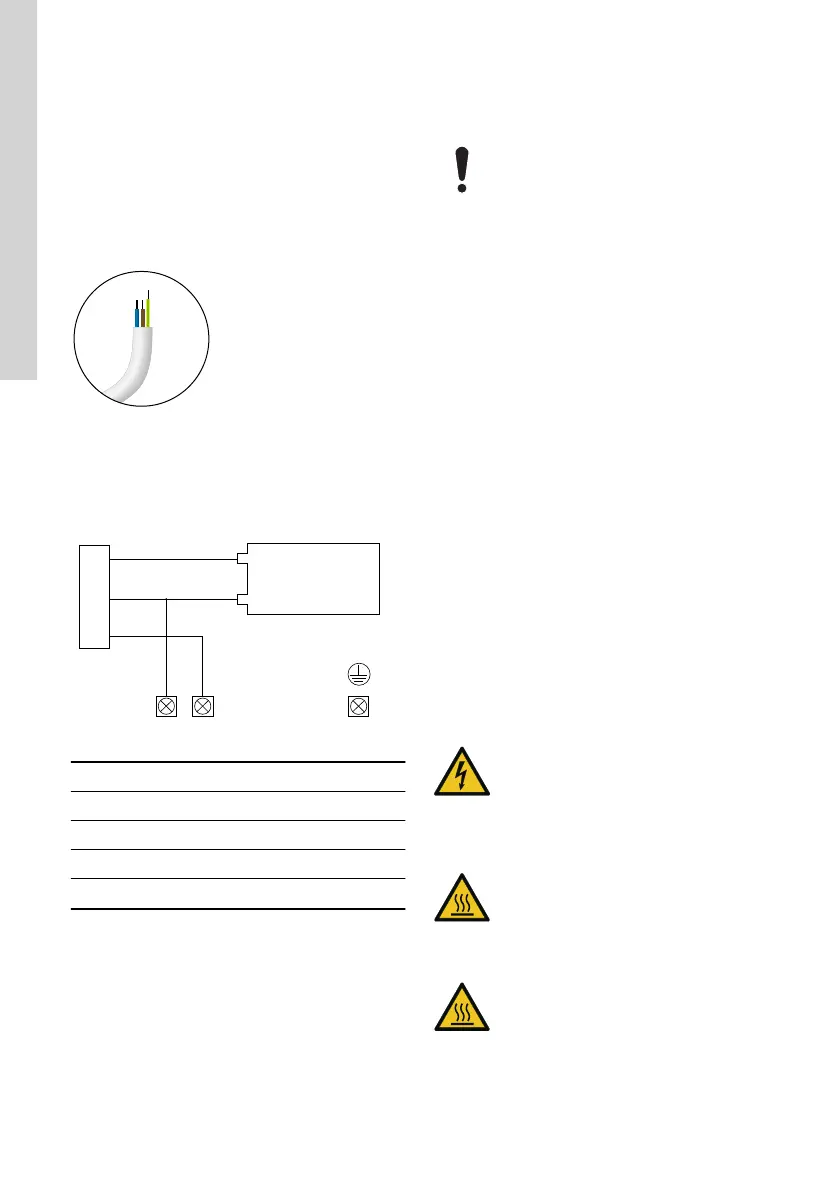
3.3.4 Wiring diagram
TM072335
Pos. Description
1 Red
2 Blue
3 Black
4 Capacitor
Related information
3.3.3 Connecting products without a cable
3.3.5
Motor protection
The pump incorporates current- and temperature-
dependent motor protection. If the pump is running
without water, is blocked or otherwise overloaded, the
built-in thermal switch will cut out. When the motor
has cooled sufficiently, it will restart automatically.
No external motor protection is required.
3.4
Adjusting the pressure switch
The automatic pressurization groups are
provided with a factory setting that is
sufficient for most plants and
requirements. However, the setting of the
pressure switch may be adjusted to adapt
the group to meet different requirements.
1. Establish the minimum desired pressure value
(leaving the pump).
2. Set the storage tank pre-loading pressure 0.2 bar
less than the minimum pressure level. This
operation must be carried out only after having
drained all of the water out of the tank.
3. After having identified the model of pressure
switch supplied with the pump, calibrate it
following the indications below and check the
established values with a pressure gauge.
4. Loosen the larger nut completely.
5. Adjust the larger nut until you reach the desired
start pressure:
a. Clockwise: increase the start pressure.
b. Counterclockwise: decrease the start
pressure.
6. Adjust the smaller nut until you reach the desired
stop pressure:
a. Clockwise: increase the stop pressure.
b. Counterclockwise: decrease the stop
pressure.
4. Startup of the product
WARNING
Electric shock
Death or serious personal injury
‐ Do not use the product for cleaning
and other maintenance of swimming
pools or similar places if there are
people in the water.
CAUTION
Hot surface
Minor or moderate personal injury
‐ Use protective gloves if the liquid or
ambient temperature is higher than 40
°C.
CAUTION
Hot surface
Minor or moderate personal injury
‐ Do not run the pump continuously with
a closed inlet or outlet valve.
12
English (GB)