6
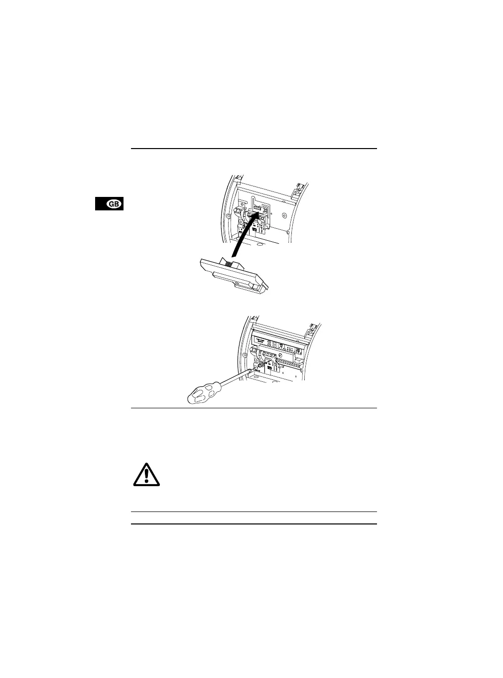
3. Fit the module.
n
TM02 0241 0904
o
TM02 0242 0904
4. Connect the cables.
Cable specifications are stated in section 5. Technical data.
A wiring diagram can be found on page 49.
• Wires connected to
- outputs NC, NO, C,
- inputs Start/stop, A, B and
- supply terminals
must be separated from each other and from the supply by re-
inforced insulation.
• All wires connected to a terminal block must be tied up at the
terminals.
5.
Switch on the electricity supply.

 Loading...