4
CONTENTS
Page
1. Symbols used in this document 4
2. General description 4
3. Replacement of control box 4
3.1 Changing the control box position 5
4. Replacement of expansion module 5
5. Replacement of pump head 6
6. Start-up 6
7. Megging 7
8. Disposal 7
1. Symbols used in this document
2. General description
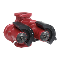
These instructions describe how to replace the
control box, expansion module and pump head of
the pumps MAGNA 32-120, 40-120, 50-120, 65-120,
50-60 and 65-60.
See also installation and operating instructions for
the pumps.
The figures from A to K can be found on the fold-out
page at the end of this booklet. In most figures only a
single-head pump is shown, but all dismantling and
assembly instructions apply to both single-head and
twin-head pumps.
3. Replacement of control box
The figures from A to K can be found on the fold-out
page at the end of this booklet.
Dismantling
Twin-head pumps: It is recommended to remove
the right control box temporarily if the left control box
is to be replaced. See fig. 1.
Fig. 1 Removing the control box
1. Check that the version number (a) of the new
control box is identical to that of the existing
control box. See fig. A.
2. Switch off the electricity supply to the pump, and
make sure that it cannot be accidentally switched
on during replacement.
3. Remove the screws (c) from the control box
cover, and open the cover. See fig. B.
4. Before wires are disconnected, carefully note
their position.
5. Remove the expansion module, if any. See
section 4. Replacement of expansion module.
6. Remove all wires from the control box.
7. Remove the three screws (d) securing the control
box to the pump head. See fig. B.
The control box may stick to the pump head.
Therefore, it may be necessary to prise the
control box loose with a small screwdriver.
Assembly
To ensure the necessary thermal connection, the
contact face of the pump head must be thoroughly
cleaned and covered with the heat-conducting paste
supplied.
1. Clean the contact face (e) of the pump head with
the cleaning serviettes. See fig. C.
2. Apply an even layer of the paste in the syringe (f)
to the contact face of the pump head. See fig. D.
3. Cover the whole contact face with paste by
moving the spatula (g) once across the contact
face. See fig. E.
Warning
Before beginning replacement of pump
parts, these instructions should be
studied carefully. Installation and
operation must comply with local
regulations and accepted codes of
good practice.
Warning
If these safety instructions are not
observed, it may result in personal
injury!
Caution
If these safety instructions are not
observed, it may result in malfunction
or damage to the equipment!
Note
Notes or instructions that make the job
easier and ensure safe operation.
Caution
The electrical connections should be
carried out in accordance with local
regulations.
Warning
Never make any connections in the
pump control box unless the electricity
supply has been switched off for at
least 5 minutes.
Make sure that voltage supplies from
other external systems have been
switched off as well.
TM02 2532 4401
 Loading...