English (GB)
10
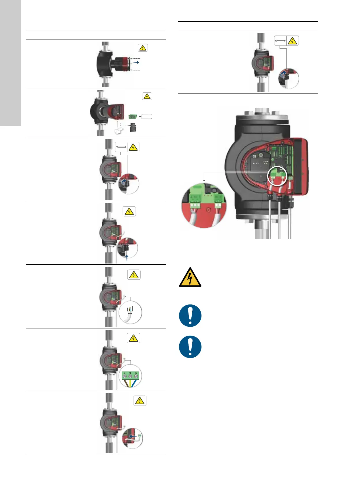
3.4.3 Connection to the power supply
3.4.4 Connection to external control
Fig. 14 Wiring diagram
Step Action Illustration
1
Remove the front
cover from the
control box.
Do not remove the
screws from the
cover.
TM05 5530 3016
2
Locate the power
supply plug and
cable gland in the
small cardboard
box supplied with
the pump.
TM06 8049 0717
3
Connect the cable
gland to the
control box.
TM06 8050 0717
4
Pull the power
supply cable
through the cable
gland.
TM06 8051 0717
5
Strip the cable
conductors as
illustrated.
TM06 8052 0717
6
Connect the cable
conductors to the
power supply plug.
TM06 8053 0717
7
Insert the power
supply plug into
the male plug in
the control box.
TM06 8054 0717
7 mm
20 mm
7 mm
25 mm
Min. Ø 7 mm
Max. Ø 14 mm
8
Tighten the cable
gland.
Refit the front
cover.
TM06 8061 0717
TM06 8060 0717
WARNING
Electric shock
Minor or moderate personal injury
- Separate wires connected to supply terminals,
outputs NC, C and start-stop input from each other
and from the supply by means of reinforced
insulation.
Make sure that all cables are heat-resistant up to
75 °C.
Install all cables in accordance with EN 60204-1
and EN 50174-2:2000.
Connect all cables in accordance with local
regulations.
Step Action Illustration
 Loading...


