7
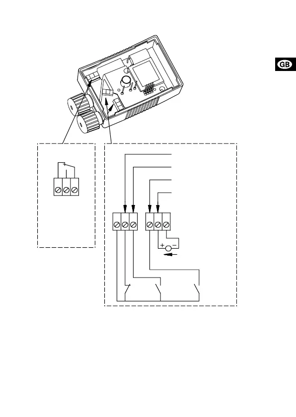
Fig. 1
Note: If the 0-10 V input is used (terminals 11 and 12), there must be a con-
nection across terminals 7 and 9 (the input for the min. curve must be
closed).
3. External analog 0-10 V controller
The MC 40/60 has an input for an external 0-10 VDC analog signal transmit-
ter (terminals 11 and 12). Via this input, the pump can be controlled by an
external controller if the pump has been set to one of the following control
modes:
TM01 1082 4401
NC
NO
C
213
9
87
10
11
12
DC 0-10 V
1
2
3
7
8
10
11
12
9
Min. curve
(night-time duty)
Max. curve
Input for analog
0-10 V signal
Start/stop
Stop
Min.
Max.
Fault signal

 Loading...


