8
• Constant curve.
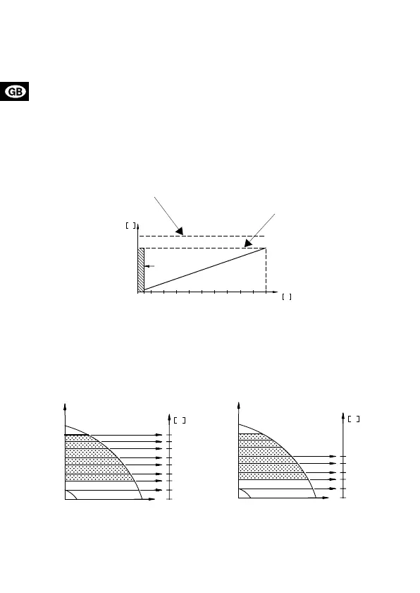
The external analog signal will set the pump curve within the range from
the min. curve to the constant curve selected according to the characteris-
tic in fig. 2.
• Constant or proportional pressure control.
The external analog signal will control the setpoint for the pump head be-
tween the setpoint corresponding to the min. curve and the setpoint se-
lected according to the characteristic in fig. 2.
At an input voltage lower than 0.5 V, the pump will operate according to the
min. curve. The setpoint cannot be changed.
The setpoint can only be changed when the input voltage is higher than
0.5 V.
Fig. 2
Note:
• The max. curve input, terminals 7 and 10, must be open.
• The min. curve input, terminals 7 and 9, must be closed.
The examples below illustrate the use of an analog control voltage in con-
nection with a pump in constant-pressure control mode:
Fig. 3
Note: As will appear from the above figure, the number of curves that can be
selected via the external analog signal will depend on the setpoint of the
pump, H
set
.
TM00 5550 4596
TM01 1384 4497
TM01 1385 4497
890107654321
m
V
H
U
Max. head/constant curve
Head set/constant curve
H
set
Min. curve
10
8,6
7,2
5,8
4,3
3,0
1,5
0,5
0
V
U
H
set
10
7,5
5,0
2,5
0,5
0
V
U
H
set

 Loading...


