9
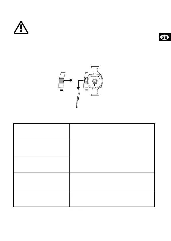
4. Fitting the module
To fit a module, remove the existing terminal box cover and fit the new cover
incorporating the module. Do not forget to remove the label.
The new cover increases the height of the terminal box by approx. 27 mm.
See fig. 4 and the figure at the end of these instructions.
Fig. 4
5. Technical data
Never make any connections in the pump terminal box unless the
electricity supply has been switched off for at least 5 minutes.
TM00 6260 4401
Start/stop input
External potential-free switch.
Contact load: 5 VDC, 0.1 mA.
Screened cable.
Loop resistance: Maximum 130 Ω/km.
Logical levels:
Logical zero: U < 1.5 V.
Logical one: U > 4.0 V.
Max. curve input
Min. curve input
Fault signal output
Internal potential-free changeover contact.
Maximum load: 250 V, 2 A, AC1.
Minimum load: 5 VDC, 1 mA.
Screened cable.
Input for analog
0-10 V signal
External signal: 0-10 VDC.
Maximum load: 0.1 mA.
Screened cable.
Subject to alterations.

 Loading...


