English (GB)
2
English (GB) Service instructions
Original service instructions
CONTENTS
Page
1. Symbols used in this document
The text accompanying the three hazard symbols DANGER,
WARNING and CAUTION is structured in the following way:
2. Identification
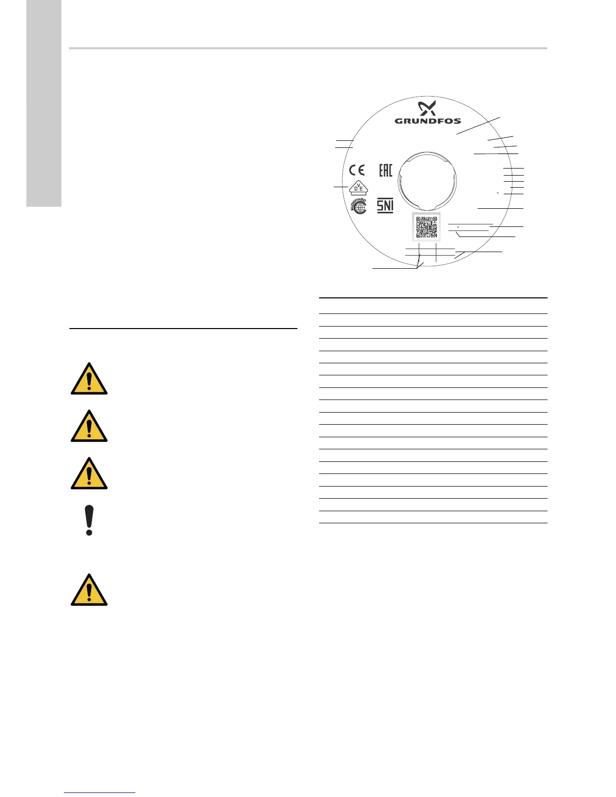
2.1 Nameplate
Fig. 1 Example of nameplate
1. Symbols used in this document
2
2. Identification
2
2.1 Nameplate
2
2.2 Type key
3
3. Service tools
4
3.1 Standard tools
4
4. Lubricants
4
5. Dismantling and assembly
5
5.1 General information
5
5.2 Removing the control box cover
5
5.3 Removing the pressure tank
5
5.4 Removing the chamber stack
7
5.5 Removing the shaft seal
7
6. Fitting the shaft seal
7
6.1 Fitting the chamber stack
8
6.2 Fitting the pressure tank
8
6.3 Fitting the control box cover
9
7. Fault finding the product
10
7.1 Grundfos Eye operating indications
10
7.2 Fault resetting
10
7.3 Fault finding chart
11
8. Exploded view
13
DANGER
Indicates a hazardous situation which, if not avoided,
will result in death or serious personal injury.
WARNING
Indicates a hazardous situation which, if not avoided,
could result in death or serious personal injury.
CAUTION
Indicates a hazardous situation which, if not avoided,
could result in minor or moderate personal injury.
If these instructions are not observed, it may result in
malfunction or damage to the equipment.
SIGNAL WORD
Description of hazard
Consequence of ignoring the warning.
- Action to avoid the hazard.
TM06 4340 2015
Pos. Description
1 Type designation
2 Product number
3 Serial number
4 Production code, year and week
5 Maximum head
6 Minimum head
7 Rated head
8 Rated flow rate
9 Maximum ambient temperature
10 IP class
11 Maximum operation pressure
12 Maximum liquid temperature
13 Minimum and maximum rated power
14 Model
15 Voltage and frequency
16 Approvals
17 Minimum and maximum rated current

 Loading...