English (GB)
6
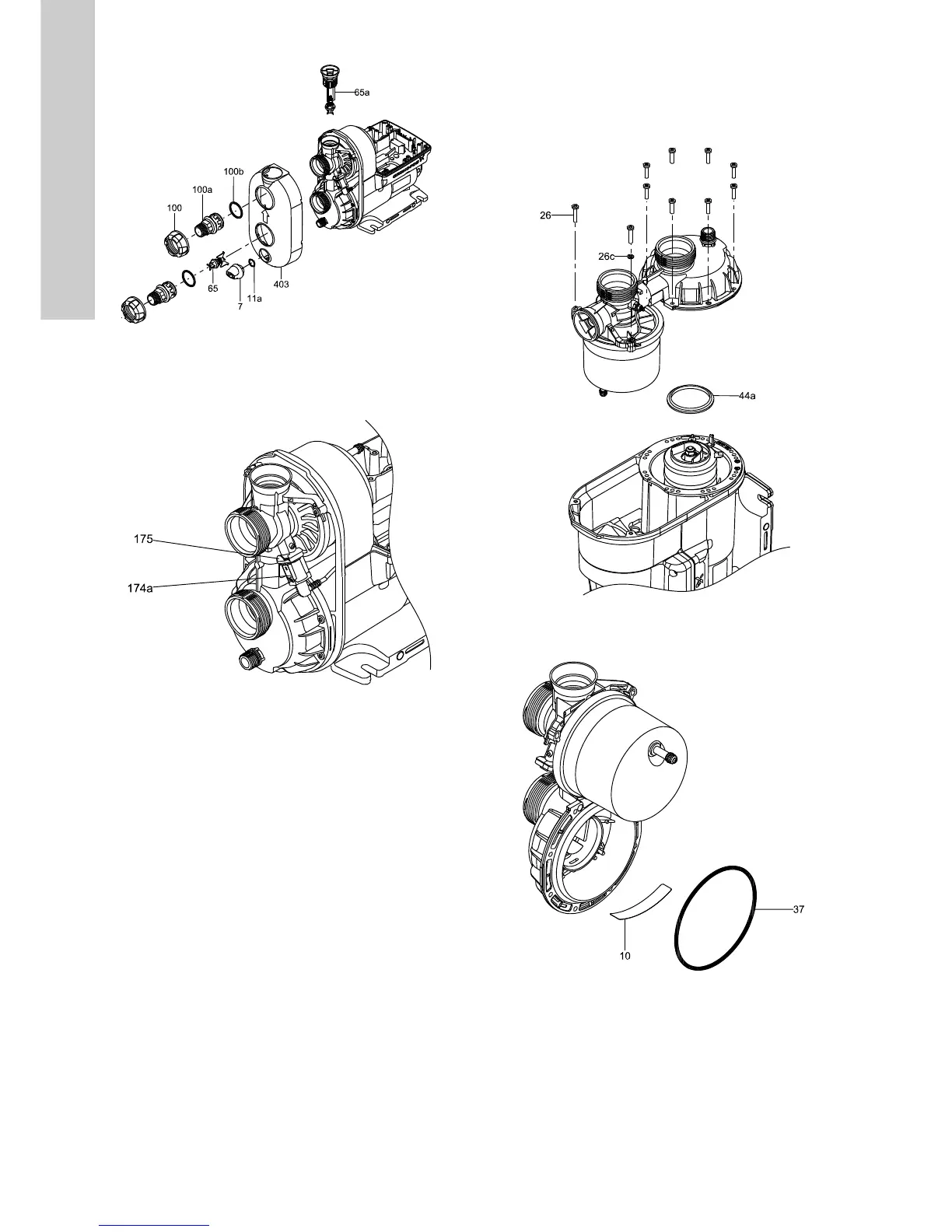
Fig. 5 Removing the nipples and the cover
8. Remove the retaining clip (175) for the sensor and remove the
sensor (174a).
9. Remove the sensor (174a).
Fig. 6 Sensor and retaining clip
10. Remove the screws (26) that hold the connection part. Note
that one of the screws holds the earth connection bracket
(173c) and washer.
11. Remove the connection part and the pressure tank.
12. Remove the seal ring (44a).
Fig. 7 Removing the connection part
13. Remove the self-priming valve (10) and O-ring (37).
Fig. 8 Self-priming valve and O-ring for connections part
TM06 5150 3915TM06 5152 3915
TM06 5149 3915TM06 5153 3915
 Loading...