English (GB)
9
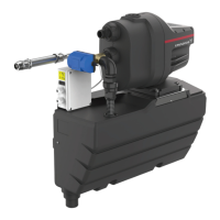
6. Fit the sensor (174a) and fasten it by means of the retaining
clip (175).
Fig. 20 Sensor and retaining clip
7. Press the pump cover back onto the pump housing.
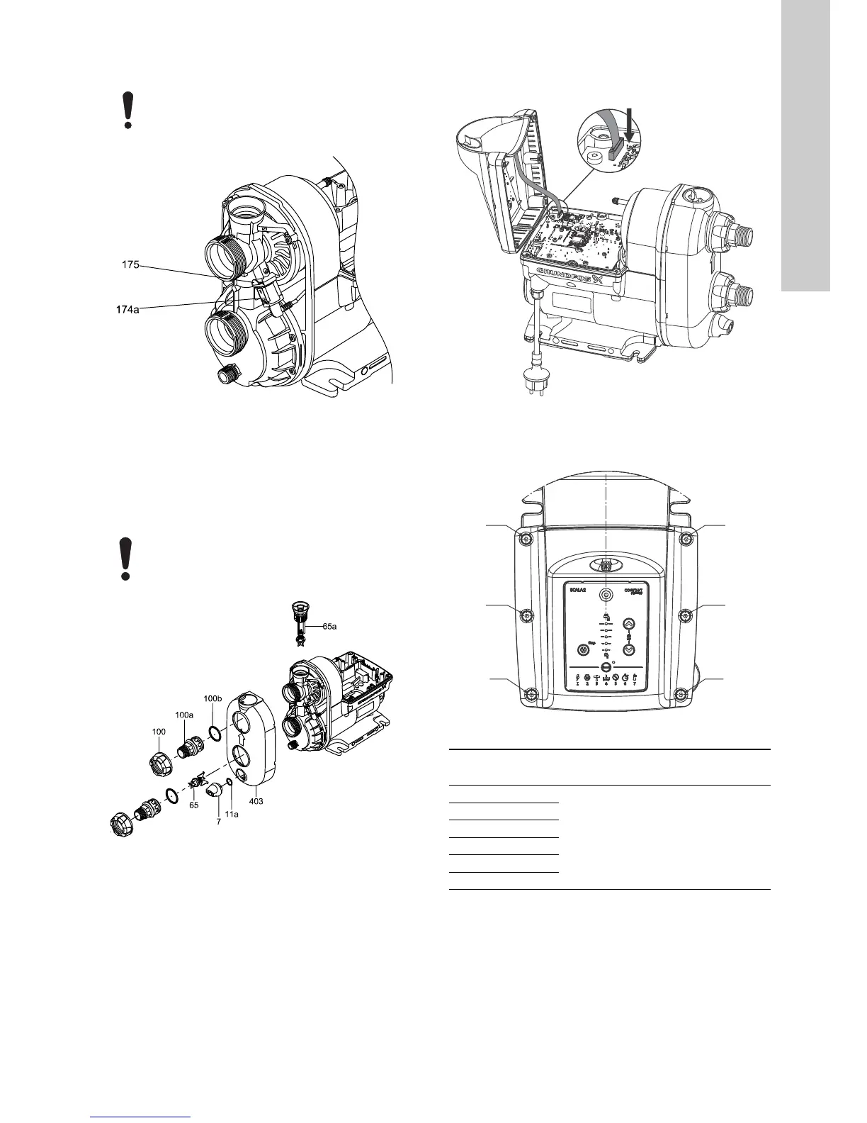
8. Fit new O-rings to the valves, nipples and plugs.
9. Fit the inlet valve in the connection part.
10. Press the nipples into the connection part, fit the union nuts
and tighten them by hand.
11. Fit the drain plug (7) and the non-return valve (65a).
Fig. 21 Fitting the nipples and the cover
6.3 Fitting the control box cover
1. Connect the HMI plug and place the control box cover on the
pump.
Fig. 22 Connecting the HMI plug
2. Cross-tighten the six pan-head torx screws according to the
table below.
Fig. 23 Tightening sequence
Check that the rubber sensor pocket is are seated
correctly.
TM06 5152 3915
Always tighten plastic nuts and plugs by hand so as
not to break the material.
TM06 5150 3915
TM06 5150 3915TM06 4959 0516
Sequence
Torque
[Nm]
1
2 ± 0.25
2
3
4
5
6

 Loading...