English (GB)
23
8.5 Moisture switch
All pumps are fitted with a moisture switch as
standard with the moisture switch being connected
via the supply cable, see section 8. Electrical
connection, and connected to a separate circuit
breaker.
The moisture switch is positioned in the bottom of
the motor. If there is moisture in the motor, the switch
will break the circuit and send a signal to the IO 113.
The moisture switch is non-reversing and must be
replaced after use.
The moisture switch is connected to the control
cable, and it must be connected to the safety circuit
of the separate pump controller. See section
8. Electrical connection.
8.6 IO 113
IO 113 provides an interface between a Grundfos
wastewater pump equipped with sensors and the
pump controller(s). The most important sensor status
information is indicated on the front panel.
One pump can be connected to one IO 113 module.
Together with the sensors, the IO 113 provides a
galvanic isolation between the motor voltage in the
pump and the connected controller(s).
IO 113 can do the following as standard:
• Protect the pump against overheating.
• Monitor the status of these items:
– motor winding temperature
– leakage (WIO)
– moisture in pump.
• Measure the stator insulation resistance.
• Stop the pump in case of alarm.
• Remotely monitor the pump via RS-485
communication (Modbus or GENIbus).
• Control the pump via a frequency converter.
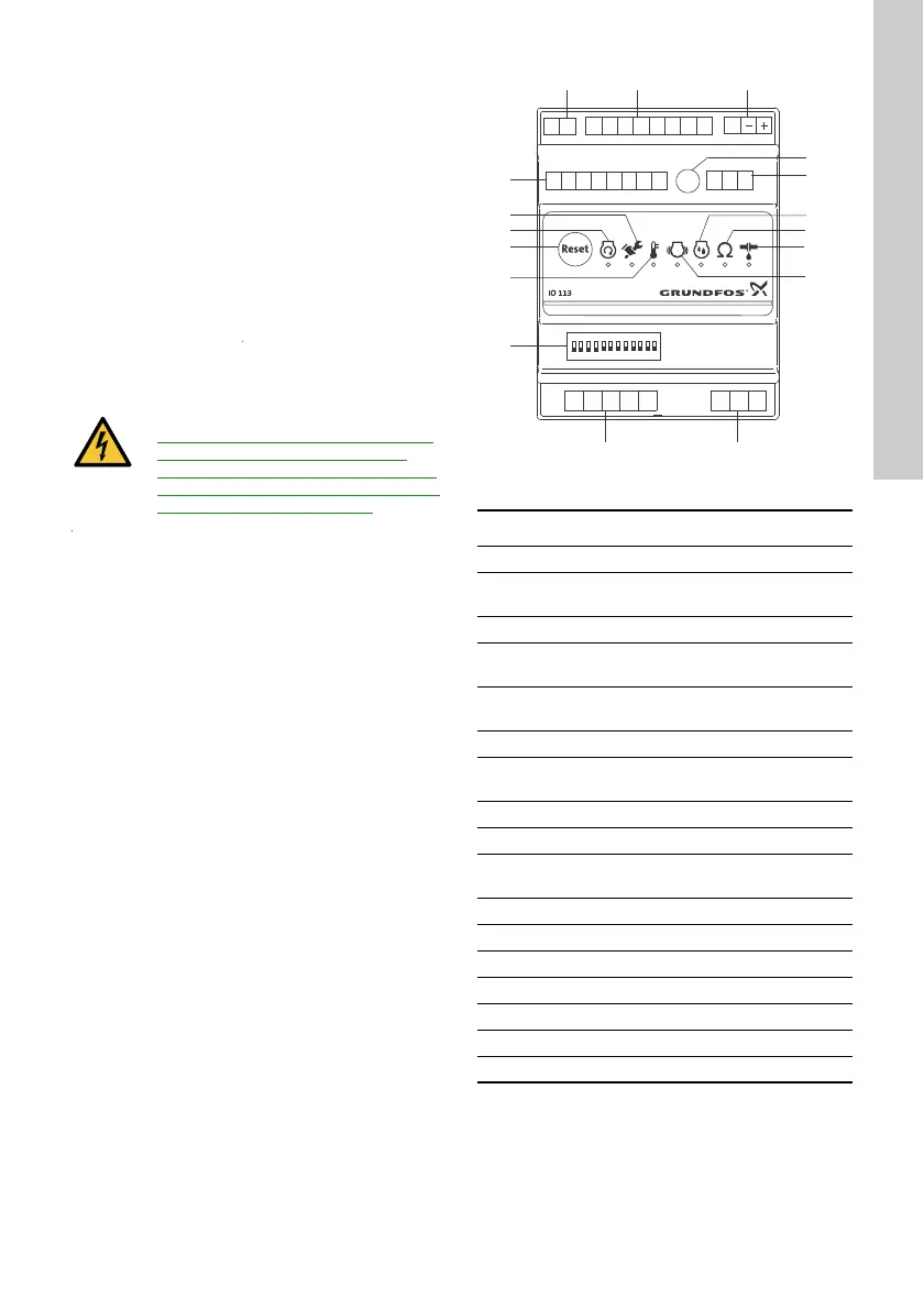
Fig. 11 IO 113 module
CAUTION
Electric shock
Minor or moderate personal injury
- The motor-protective circuit breaker of
the pump controller must include a
circuit which automatically disconnects
the power supply in case the protective
circuit for the pump is opened.
TM05 1881 3811
Pos. Description
1 Terminals for alarm relay
2
Terminals for analog and digital inputs and
outputs
3 Terminals for supply voltage
4
Potentiometer for setting the warning limit
of stator insulation resistance
5
Terminals for RS-485 for GENIbus or
Modbus
6 Indicator light for moisture measurement
7
Indicator light for stator insulation
resistance
8 Indicator light for leakage (WIO)
9 Indicator light for vibration in pump
10
Terminals for measurement of stator
insulation resistance
11 Terminals for connection of pump sensors
12 DIP switch for configuration
13 Indicator light for motor temperature
14 Button for resetting alarms
15 Indicator light for motor running
16 Indicator light for service
17 Terminals for digital outputs
PET1 T2
G1 A1 G2 A2 K1 K2 R1 R2
D1 D2 D3 D4 D5 D6 D7 D8
P1 P2 P3 P4 P5
AYB
I1 I2 I3
ON DIP
12345678910
11 1 2
12 3
4
5
6
7
8
9
1011
 Loading...