English (GB)
4
2. General description
This booklet includes instructions for installation,
operation and maintenance of Grundfos SL1 and
SLV submersible sewage and wastewater pumps
with motors of 1.1 to 11 kW. Grundfos SL1 and SLV
sewage and wastewater pumps are designed for
pumping domestic, municipal and industrial sewage
and wastewater.
Two types of pumps are available:
• SL1 sewage pumps with S-tube impeller
• SLV sewage pumps with SuperVortex free-flow
impeller.
The pumps can be installed on an auto-coupling
system or stand freely on the bottom of a tank.
Grundfos SL1 and SLV pumps are designed with an
S-tube and SuperVortex impeller, respectively, to
ensure reliable and optimum operation.
The booklet also includes specific instructions for the
explosion-proof pumps.
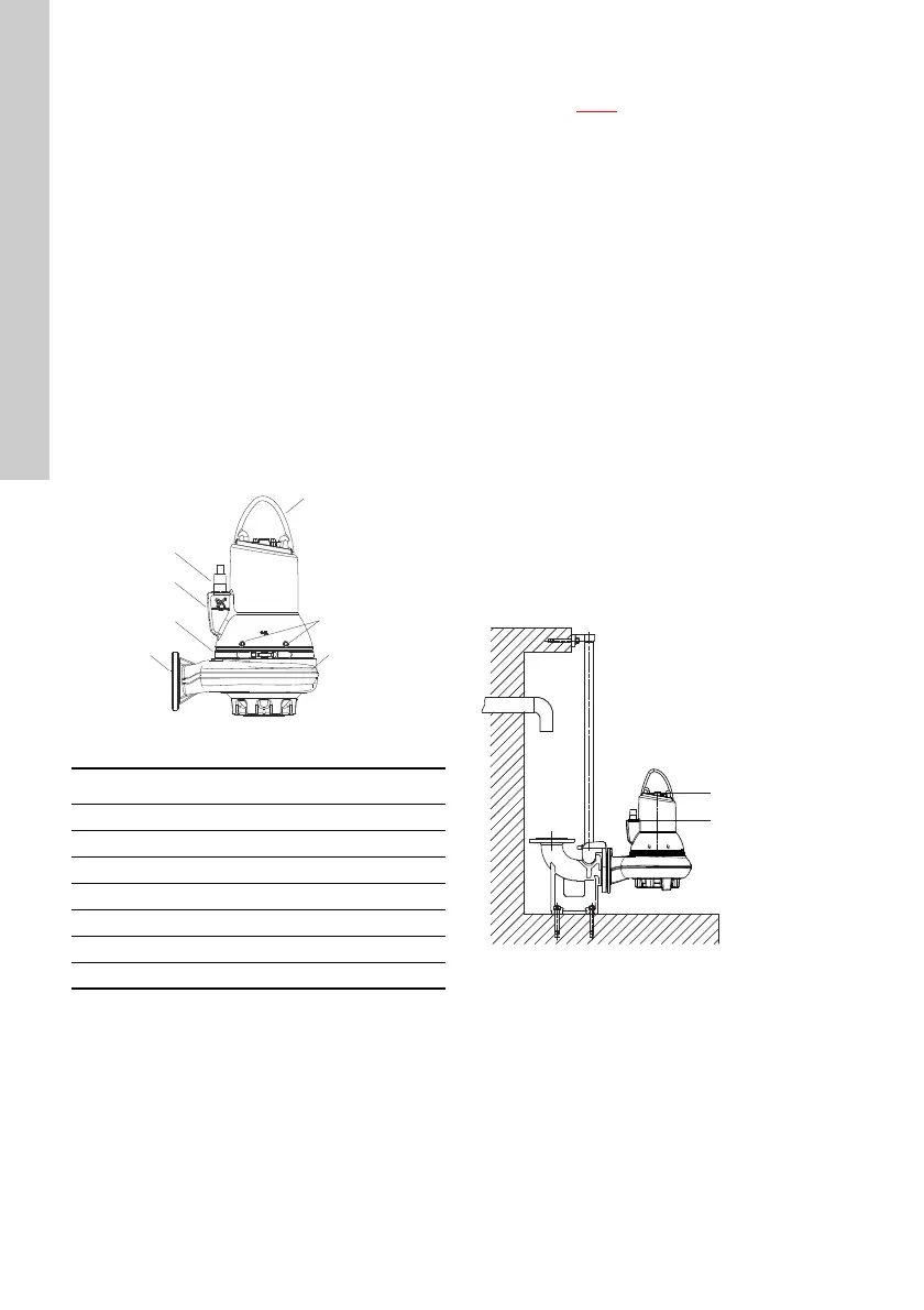
2.1 Product drawing
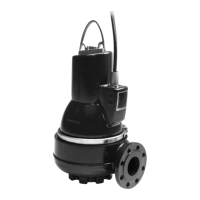
Fig. 1 SL1 pump
2.2 Control and monitoring
The pumps can be controlled via the Grundfos
controllers LC, LCD
and dedicated controls DC,
DCD. See section 8.2 Pump controllers.
Pumps with sensor are supplied together with an IO
113. See section 8.6 IO 113.
2.3 Applications
SL1 and SLV pumps are designed for pumping these
liquids:
• large quantities of drainage and surface water
• domestic wastewater with discharge from toilets
• wastewater with a high content of fibres
(SuperVortex impeller)
• municipal and commercial sewage and
wastewater.
2.4 Operating conditions
SL1 and SLV pumps are suitable for the following
operating situations:
• S1 operation (continuous operation), the pump
must always be covered by the pumped liquid to
the top of the motor. See fig. 2.
• S3 operation (intermittent operation), the pump
must always be covered by the pumped liquid up
to the top of the cable entry. See fig. 2.
For further information about S1 and S3 operation,
see section 9.2 Operating modes.
Fig. 2 Stop levels
TM04 2648 2808
Pos. Description
1 Lifting bracket
2 Nameplate
3Oil screws
4 Outlet flange
5 Cable plug
6Clamp
7 Pump housing
TM04 2649 2808
 Loading...