11
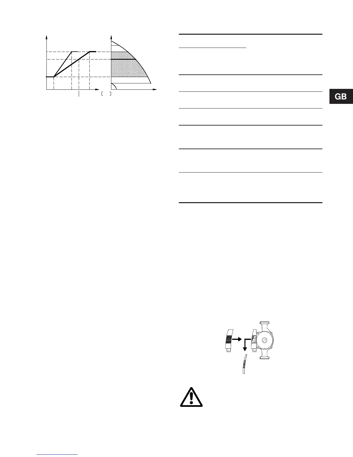
Fig. 13
In the above example, T
max.
= 80°C has been se-
lected. The actual liquid temperature T
actual
causes
the setpoint for head to be reduced from 100% to
H
actual
.
The temperature influence function requires:
• Proportional or constant pressure control mode.
• The pump must be installed in the flow pipe.
• System with flow-pipe temperature control
(e.g. according to outdoor temperature).
Temperature influence is suitable in:
• systems with variable flows (e.g. two-pipe heating
systems), in which the activation of the tempera-
ture influence function will ensure a further reduc-
tion of the pump performance in periods with small
heating demands and consequently a reduced
flow-pipe temperature, and
• systems with almost constant flows (e.g. one-pipe
heating systems and underfloor heating systems),
in which variable heating demands cannot be reg-
istered as changes in the head (as is the case
with two-pipe heating systems). In such systems,
the pump performance can only be adjusted by
activating the temperature influence function.
Selection of T
max.
In systems with a dimensioned flow-pipe tempera-
ture of:
• up to and including 55°C, select T
max.
= 50°C,
• above 55°C, select T
max.
= 80°C.
Specifically for UPE 25-40, 25-40 A and 32-40:
In the temperature range of 20 to 30°C, the pump au-
tomatically changes over to operation according to
an uncontrolled night-time duty curve.
6.6 Indicator lights
The two indicator lights are used for fault and operat-
ing indication.
For position on pump, see fig. 21, section 7.2 Control
panel.
Note: When the R100 remote control communicates
with the pump, the red indicator light will flash rap-
idly.
Functions of indicator lights:
See also section 8. Fault finding chart.
6.7 Expansion modules
The pump can be fitted with an expansion module
enabling communication with external signals (signal
transmitters).
Two types of expansion modules are available:
• Fault signal module, types MC 40/60 and MC 80.
• Bus module, types MB 40/60 and MB 80.
To fit a module, remove the existing terminal box
cover and fit the new cover incorporating the module.
The new cover increases the height of the terminal
box by approx. 20 mm, fig. 14.
Fig. 14
30%
100%
°CT
805020
H
H
Q
H
actual
T
actual
TM01 0626 1797
Indicator lights
Description Fault
(red)
Opera-
tion
(green)
Off Off
The electricity supply has
been switched off.
Off
Perma-
nently on
The pump is operating.
Off Flashing
The pump has been set
to stop.
Perma-
nently on
Off
The pump has stopped
because of a fault. Re-
starting will be attempted.
Perma-
nently on
Perma-
nently on
The pump is operating,
but it has been stopped
because of a fault.
Perma-
nently on
Flashing
The pump has been set
to stop, but it has been
stopped because of a
fault.
TM00 4463 3394
Never make any connections in the pump
terminal box unless the electricity supply
has been switched off for at least 5 min-
utes.
 Loading...