16
7. Setting the pump
For the setting of the pump, use:
• Control panel.
• R100 remote control.
• Bus communication
(not described in detail in these instructions.
Contact Grundfos).
The following table shows the application of the indi-
vidual operating units and in which section the func-
tion has been described.
“-” = not available with this operating unit.
7.1 Factory settings
7.2 Control panel
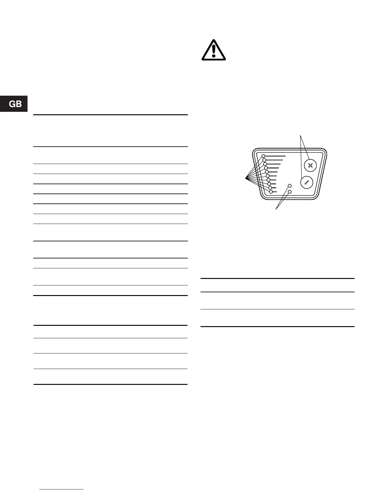
The control panel, fig. 21, incorporates the following:
• Buttons, “+” and “–”, for setting.
• Light fields, yellow, for indication of control mode
and pump head.
• Indicator lights, green and red, for operating and
fault indication, see section 6.6 Indicator lights.
Fig. 21
7.2.1 Setting of control mode
Description of function, see section 6.1 Control
modes.
When the buttons “+” and “–” are pressed simultane-
ously, the light fields will indicate the selected control
mode:
If the buttons are pressed for more than 5 sec., the
control mode will change over to constant pressure
and proportional pressure respectively.
Note:
If the pump has been set to constant curve duty and
the buttons “+” and “–” are pressed simultaneously,
the following applies:
• less than 5 sec.:
The light fields will not indicate the selected con-
trol mode.
• more than 5 sec.:
The control mode will not be changed.
Function
Control
panel
R100
Proportional pressure con-
trol
7.2.1 7.7.1
Constant pressure control 7.2.1 7.7.1
Setting of pump head 7.3 7.5.1
Max. curve duty 7.3.1 7.5.2
Min. curve duty 7.3.2 7.5.2
Constant curve duty - 7.5.2
Temperature influence - 7.7.2
Resetting of fault indica-
tions
7.3.4 7.5.3
Activation/deactivation of
pump buttons
- 7.7.3
Allocation of pump number - 7.7.4
Reading various data -
7.6.1-
7.6.6.
Start/stop 7.3.3 7.5.2
Pump type Control mode Pump head
UPE xx-40 Proportional pressure
1.8 metres at maxi-
mum flow, see fig. 23
UPE xx-60 Proportional pressure
3 metres at maximum
flow, see fig. 25
UPE xx-80 Proportional pressure
4 metres at maximum
flow, see fig. 27
At high liquid temperatures, the pump may
be so hot that only the buttons should be
touched to avoid burns.
TM00 4431 0603
Light fields Control mode
Top + bottom
light fields flashing
Proportional pressure
Middle light field(s)
flashing
Constant pressure
Indicator lights
Buttons
Light fields
 Loading...