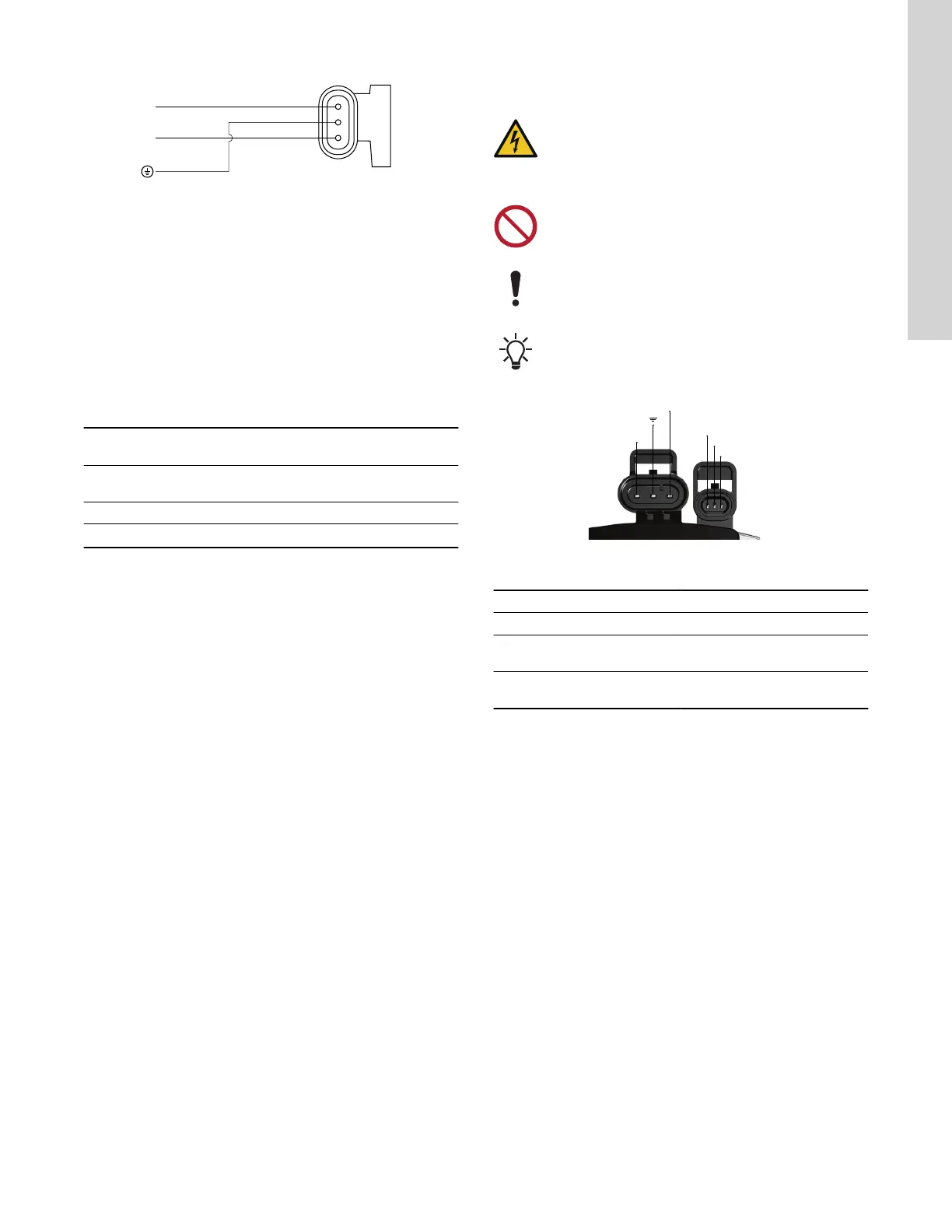
6.1.3 Wiring diagram
TM085681
6.1.4 Supply voltage
1 × 115V +10 % / -10 %, 60 Hz.
The pump can be externally controlled via PWM or 0-10 V signal, or
manually speed-controlled by adjusting to constant curve l, ll or lll.
6.1.5 Reduced supply voltage
Pump operation is ensured above 75 VAC with reduced
performance.
Pumps in internal control mode
If the voltage falls below 75 VAC, the pump stops and gives an
alarm.
If the voltage falls below 95 VAC, the pump continues running with
reduced performance.
Supply
voltage
Pump
performance
Status
LED
PWM output signal
115 VAC Running -
According to
specification.
95 VAC Reduced Yellow Warning
75 VAC Stopped -
Alarm
3)
3)
The pump starts automatically again when the voltage is above 85 VAC.
Pumps with PWM control
If the voltage falls below 95 VAC, a low-voltage warning is sent via
the PWM signal.
If the voltage falls below 75 VAC, the pump stops and an alarm
signal is sent via PWM.
6.2 Signal-cable connection
WARNING
Electric shock
Death or serious personal injury
‐ External signal cables must be in accordance with
chapter 725 of the NEC in order to insulate this circuit
from others.
Do not connect the signal reference wire to the ground.
Connect the signal wires to the correct poles. Otherwise,
the pump may be damaged.
Products that are controlled internally do not have any
active signal-cable connection and can therefore be
covered by a blanking plug.
TM064416
Connections Mini Superseal
Contact PWM 0-10 V Cable
1 PWM input Signal input (+) Brown
2
Signal
reference
Signal
reference (-)
Blue
3 PWM output
Signal output
(optional)
Black
11
English (US)