8. Control functions
8.1 Operating panel
The design of the operating panel differs based on the model. See
the images below.
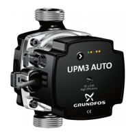
TM084127
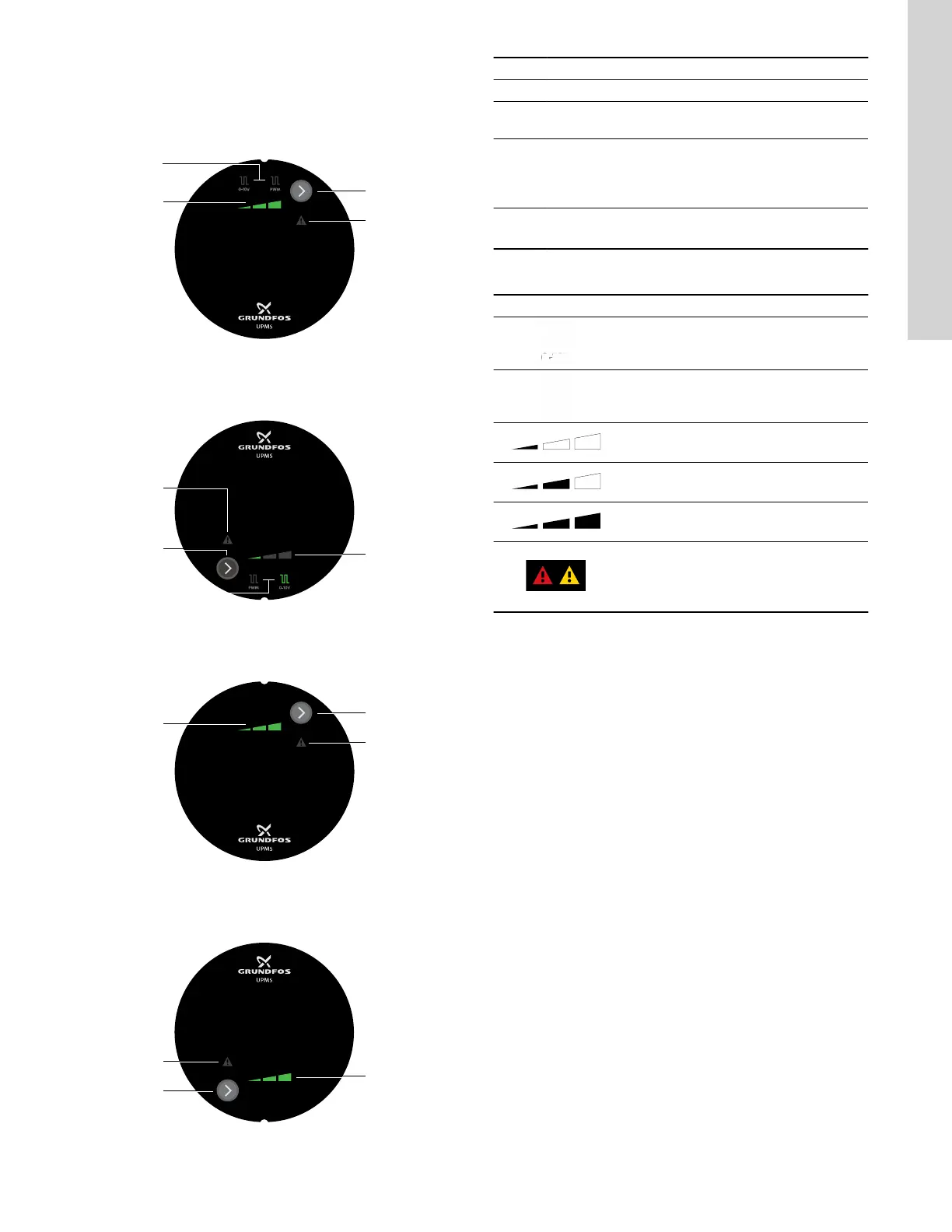
UPMS operating panel with external signal 9 o'clock control
box position
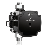
TM085623
UPMS operating panel with external signal 3 o'clock control
box position
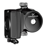
TM084186
UPMS operating panel without external signal, 9 o'clock control
box position
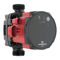
TM084187
UPMS operating panel without external signal, 3 o'clock control
box position
Pos. Description
1 Speed setting (I, II, III) for constant curve
2
Button for changing external signal (for some models)
and speed setting
3
Warning and alarm symbol
A warning is indicated with yellow, and the pump
continues operation. An alarm is indicated with red, and
the pump stops.
4
External signal
Use the button (3) to select 0-10 V or PWM.
8.1.1 Light fields indication
Active light fields Description
0-10 V
PWM
Setting I
Setting II
Setting III
Fault indication (warning = yellow / alarm =
red)
If the alarm indication is on, the pump is
stopped.
13
English (US)