8.2.2 PWM input signal profile A (heating)
At high PWM signal duty cycles, a hysteresis prevents the pump
from starting and stopping if the input signal fluctuates around the
shifting point. At low PWM signal duty cycles, the pump speed is
high for safety reasons. In case a cable breaks when mounted in
a system, the pump starts to run at maximum speed. This
is suitable for both boilers and heat pumps to ensure that the pump
transfers heat even if a cable breaks.
Max.
Min.
10
20
30 40
50 60 70
80
90
100
X
Y
TM049985
PWM input profile A (heating)
Axis Value
X Input duty cycle
Y Speed
PWM input duty cycle Pump status
PWM signal ≤ 10 % Max. speed
10 % < PWM signal ≤ 84 %
Variable speed from min. to max.
speed
84 % < PWM signal ≤ 91 % Min. speed
91 % < PWM signal ≤ 95 % Hysteresis area: on/off
95 % < PWM signal ≤ 100 % Standby mode: off
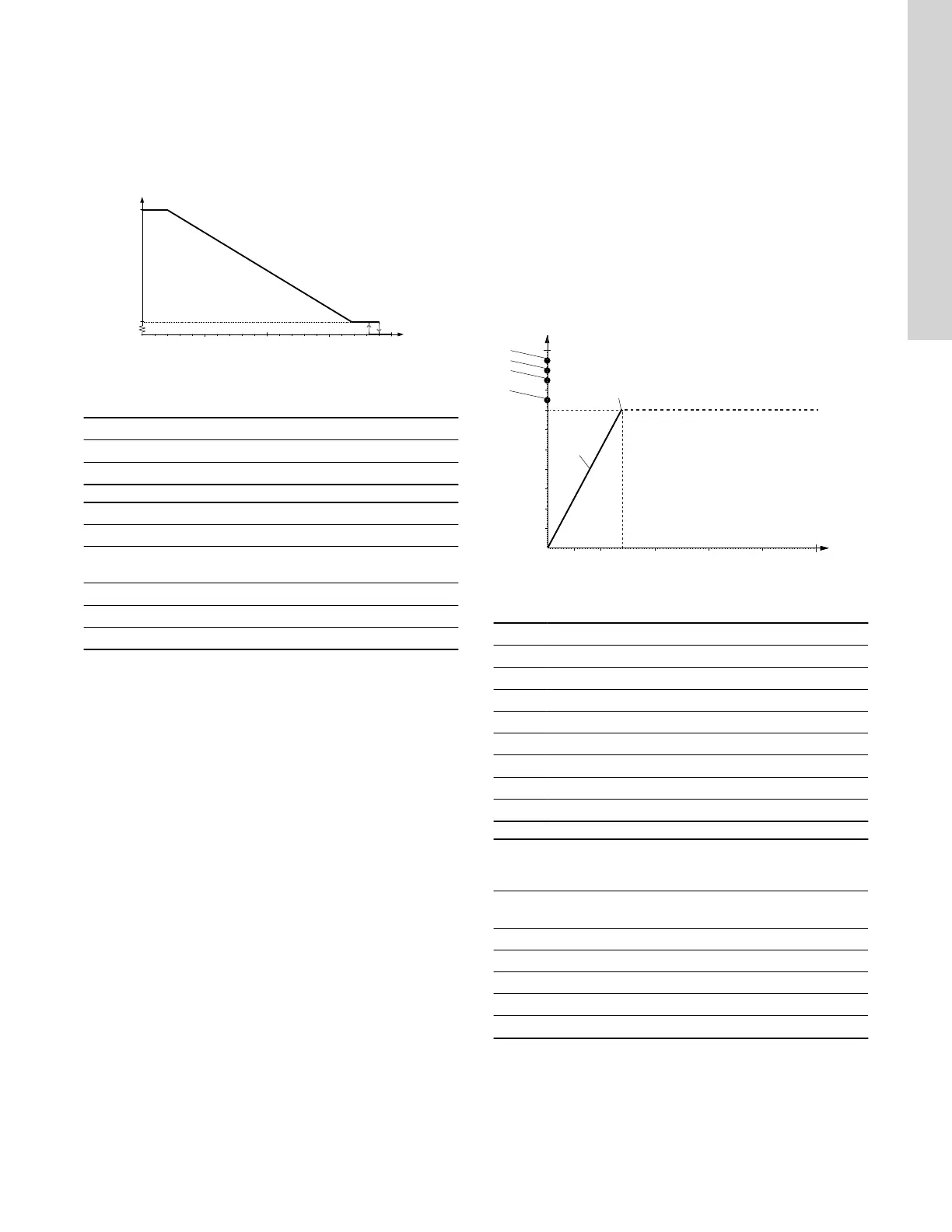
8.2.3 PWM feedback signal (standard)
The PWM feedback signal offers the same pump information as in
bus systems:
• current power consumption (accuracy ± 2 % of PWM signal)
• warning
• alarm
• operating status.
Alarms
Alarm output signals are available because some PWM output duty
cycles are dedicated to alarm information. If a supply voltage is
measured below the specified supply voltage range, the output duty
cycle is set to 75 %. If the rotor is locked due to deposits in the
hydraulics, the output duty cycle is set to 90 % as this alarm has a
higher priority.
F
E
100
90
80
70
60
50
40
30
20
10
25 50 100 150
200
250
[W]
[%]
A
B
C
D
TM050006
PWM feedback signal, UPMS power consumption
Pos. Description
X-axis Output power consumption [W]
Y-axis Output duty cycle in percentage [%]
A Standby (stop)
B Alarm stop: fault, blocked pump
C Alarm stop: electrical fault
D Warning
E Slope: 1 W / % PWM signal
F Saturation at 70 W
PWM
output duty
cycle
QT
[s]
Pump information
DT
[s]
Priority
95 0
Standby (stop) by PWM duty
cycle
0 1
90 30 Alarm, stop, blocked error 12 2
85 0-30 Alarm, stop, electrical error 1-12 3
75 0 Warning 0 5
0-70 0-70 W (slope 1 W / % PWM) 6
Output frequency: 75 Hz ± 5 %
QT = qualification time, DT = disqualification time
15
English (US)