8.2.4 0-10 VDC
The UPMS circulators can be externally speed-controlled by an
analog 0-10 VDC signal.
The pump requires a 0-10 V signal on the signal port to control the
speed of the pump. The pump will run at its maximum speed if the
signal fails (cable break).
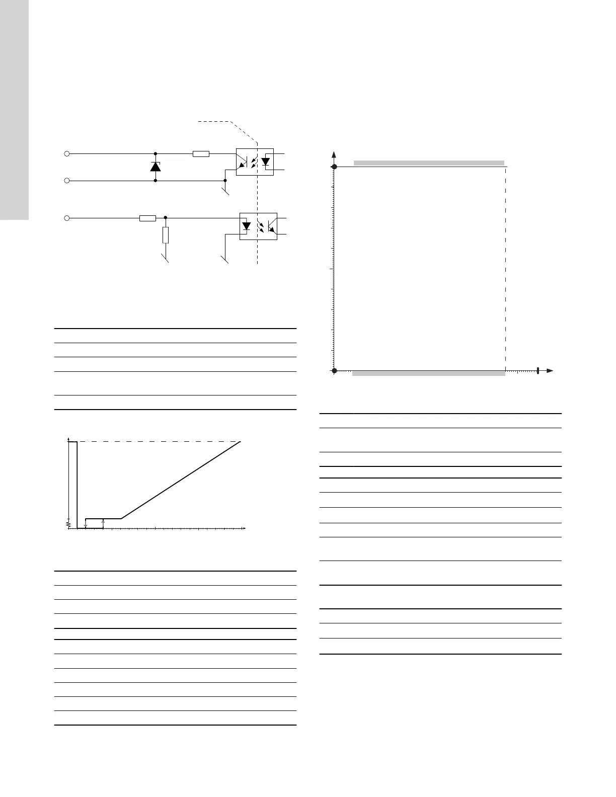
TM085628
Schematic drawing, equivalent interface
Pos. Description
1 Galvanic isolation
2 Alarm output signal
3
Signal reference (without connection to protective
ground)
4 0-10 VDC input
Profile R
0.5 4 5
U[V]
1 2 3 96 7 8 10
1
2
3
TM070784
Profile R
Pos. Description
1 Max.
2 Min.
3 Stop
U [V] Pump status
0 < U ≤ 0.5 Max. speed
0.5 < U ≤ 1 Standby (Stop)
1 < U ≤ 2 Hysteresis
2 < U ≤ 3 Min. speed
3 < U ≤ 10 Speed between min. and max.
Alarm output signal
An alarm output signal is available.
Output transistor status indicates pump operation.
The output signal is activated in the following cases:
• The pump stops when the input signal is between 0.5 and 2 V.
• The pump stops because of an alarm and the input signal is
between 2 and 10 V.
Output signal is not activated in the following cases:
• Pump fault.
• The pump is running (input voltage is above 0.5 V).
TM070578
Output profile 0-10 VDC
Pos. Alarm output signal % Description
A 100
Standby (stop) or alarm
stop
B 0 Pump is running.
0-10 VDC Symbol Value
Operating voltage
U
I
0-10 V
Input impedance
Z
I
≥ 50 kΩ
Max input voltage - 26 V
Continuous short
circuit protection
- Yes
Reverse polarity
protection
-
Yes, Limit: 26 V, 20
mA
Alarm output signal
State
Symbol Value
Off
Z
O, off
> 100 kΩ
On
Z
O, on
< 500 Ω
16
English (US)