28
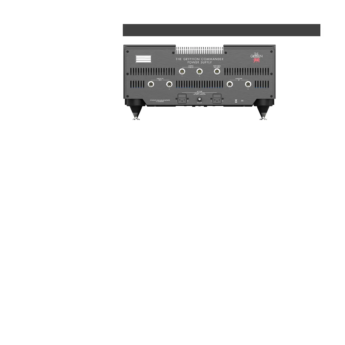
ANALOG PSU 1 LEFT and RIGHT
Analog power supply output for Commander Preamplifier.
ANALOG PSU 2 LEFT and RIGHT
Analog power supply output for Legato, Legato Legacy or future source components.
CONTROL INTERFACE 1
Power supply output for the Commander control circuits.
CONTROL INTERFACE 2
Power supply output for future source component's control circuits
LINEAR DIGITAL DAC SUPPLY
Linear power supply output for future source components.
GROUND
Binding post for chassis ground.
Mains input sockets:
Two IEC appliance C14 inlets (for power cords with IEC C13 receptacle)
AC FUSE holders and fuse values:
100-120Vac: T1A / 250V 220-240Vac: T500mA / 250V
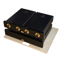
Commander Power Supply Rear Panel