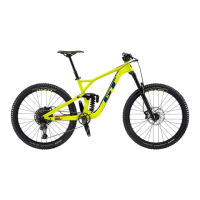
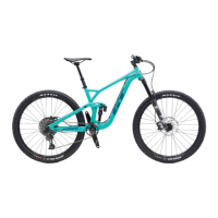
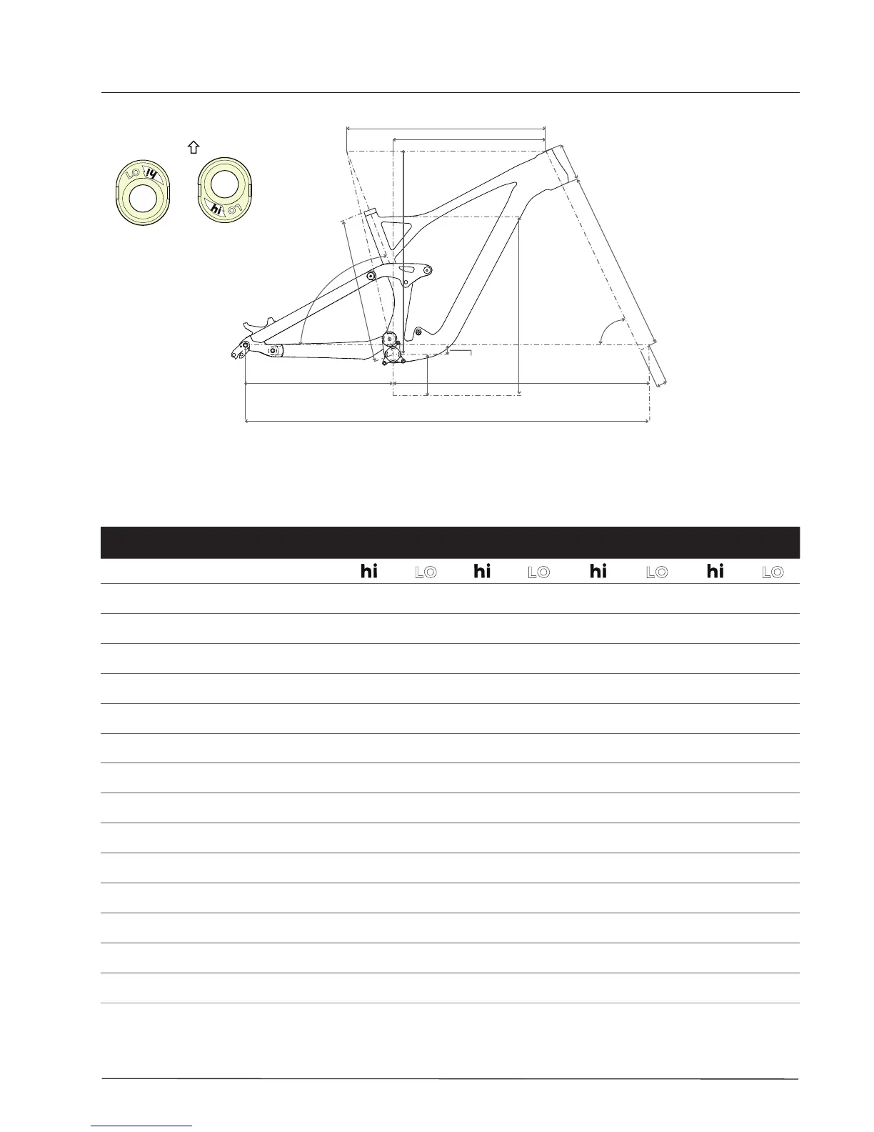
Frame Size S M L XL
Flip Chip Orientation
D Seat Tube Length
392 392 400 400 430 430 480 480
C Top Tube Horizontal
565 567 592 593 619 620 647 647
A Head Tube Angle
65.98° 65.5° 65.97° 65.5° 65.96° 65.5° 65.95° 65.5°
B Seat Tube Angle
76.48° 76° 76.47° 76° 76.46° 76° 76.45 76°
G Standover
750 740 760 760 770 770 805 805
H Head Tube Length
102 102 110 110 118 118 126 126
F Wheelbase
1164.76 1166 1193.07 1194 1121.39 1222 1249.71 1251
M Front Center
731.94 732 760.24 760 788.54 789 816.84 817
E Chainstay Length
433.62 435 433.62 435 433.62 435 433.62 435
L Bottom Bracket Drop
20.86 27 20.78 27 20.7 27 20.62 27
K Bottom Bracket Height
356.56 349 356.72 349 356.8 349 356.9 349
J Fork Rake
51 51 51 51 51 51 51 51
L Stack
583.86 587 591.97 595 598.54 602 605.36 609
M Reach
424.91 420 449.86 445 474.8 470 499.75 495
Geometry - Sensor 29
A
 Loading...