GDS-1000A-U Series User Manual
90
Vertical View (Channel)
The Vertical view section describes how to set the vertical scale,
position, bandwidth limitation, coupling mode, and attenuation.
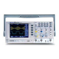
Moving the waveform position vertically
To move the waveform up or
down, turn the vertical position
knob for each channel.
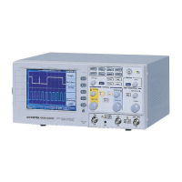
Selecting the vertical scale
To change the vertical scale,
turn the VOLTS/DIV knob; left
(down) or right (up).
2mV/Div ~ 10V/Div, 1-2-5 increments
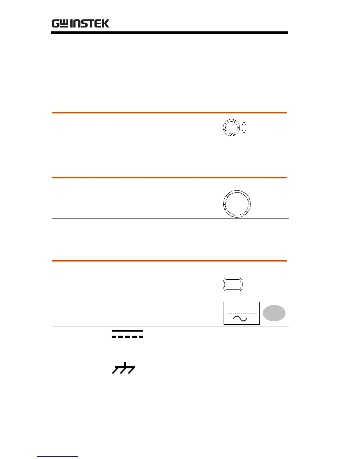
Selecting the coupling mode
1. Press the Channel key.
2. Press Coupling repeatedly to
select the coupling mode.
DC coupling mode. The whole
portion (AC and DC) of the signal
appears on the display.
Ground coupling mode. The display
shows only the zero voltage level as a
horizontal line. This mode is useful
for measuring the signal amplitude
with respect to the ground level.
 Loading...