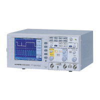
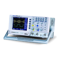
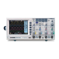
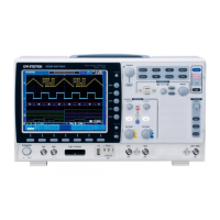
GDS-800 Series Digital Storage Oscilloscope Operation Manual
11
AUTOSET
The “Autoset” function provides a stable, triggered display of any input signal
(almost). User can connect a signal to either the channel 1 or channel 2 input BNC
connectors and press AUTOSET button. Table 3-1 shows the defaults of “Autoset”
function
Table 3-1: Defaults of “Autoset” function
Control Modified by Autoset
Acquire Sample
Acquire stop after RUN/STOP button only
Display style Vectors
Display format YT
Horizontal position Centered within the graticule windows
Horizontal Scale As determined by the signal frequency
Trigger coupling DC
Trigger level Midpoint of data for the trigger source
Trigger position Center
Trigger slope Positive
Trigger source Highest frequency if both channel available
Trigger type Edge
Vertical bandwidth Full
Vertical coupling DC or AC (depend on the signal)
Vertical offset 0 V
Vertical scale As determined by the signal level
 Loading...
