GDS-800 Series Digital Storage Oscilloscope Operation Manual
13
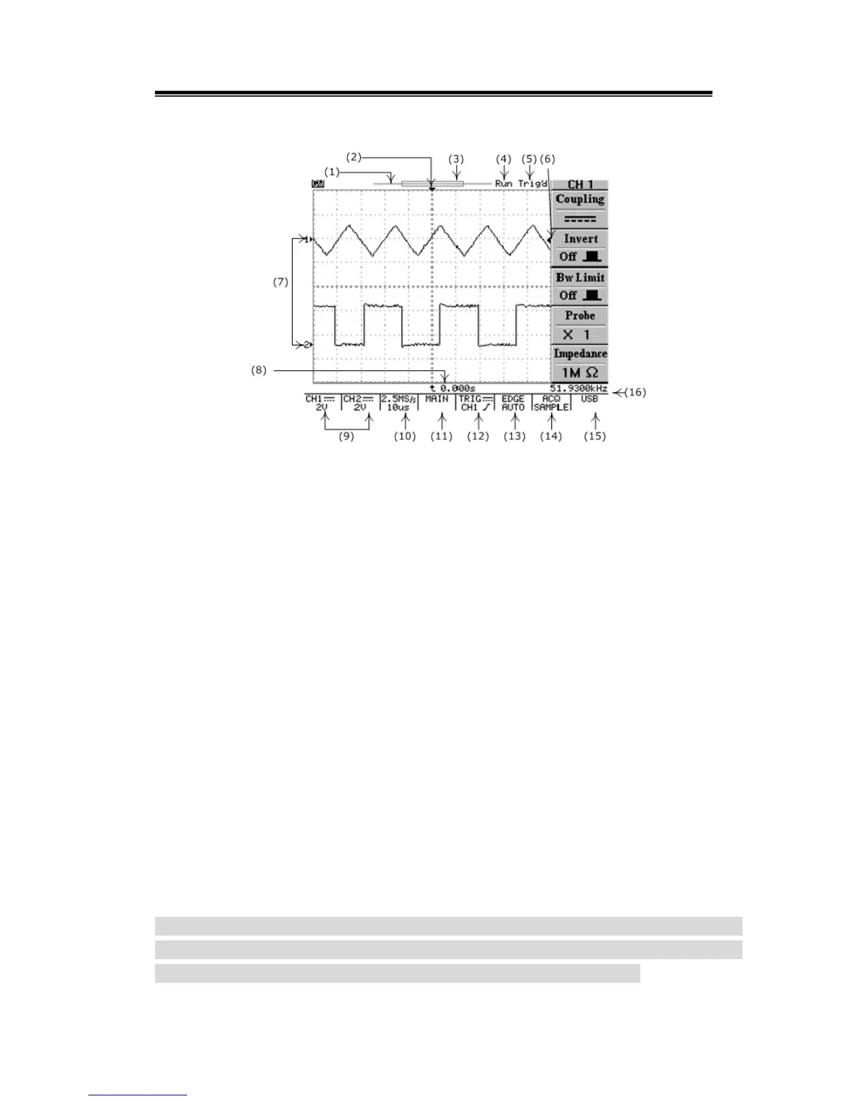
Display Area
(1): The memory bar (500 point processed by oscilloscope)*.
(2): Trigger position (T) indicator
(3): Viewable area shows segment of memory bar which been displayed*. Please
refer page 40 for details.
(4): Run/Stop mode indicator
(5): Trigger status
(6): Trigger level indicator
(7): Channel position indicator
(8): Delay trigger indicator
(9): Status display for channel 1 & 2
(10): Sample rate status readout
(11): Horizontal status readout
(12): Trigger source and status readout
(13): Trigger type and mode readout
(14): Acquisition status
(15): Interface type indicator
(16): Trigger Frequency counter
*: The memory bar is always 500 points under RUN mode even the memory
length is selected over 500 points, the oscilloscope is still displaying
250points or 300points (menu off) on LCD screen waveform area.

 Loading...