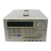
PSM-SERIES PROGRAMMABLE POWER SUPPLY
USER MANUAL
42
5-5. Test Lead
Table 1:
Model PSM-2010 PSM-3004 PSM-6003
Test Lead
GTL-104 or GTL-204
(The maximum current: 10A)
Note: The attached test lead to the PSM-SERIES is only used for the front
panel output terminal with the maximum current of 10A.
Table (2)
AWG
10 12 14 16 18 20 22 24 26 28
Maximum
Current(amps)
40 25 20 13 10 7 5 3.5 2.5 1.7
mΩ/m
3.3 5.2 8.3 13.2 21.0 33.5 52.8 84.3 133.9 212.9
PSM-SERIES PROGRAMMABLE POWER SUPPLY
USER MANUAL
43
6. MAINTENANCE
The following instructions are executed by qualified personnel only. To
avoid electrical shock, do no perform any servicing other than the operating
instructions unless you are qualified to do so.
6-1. Fuse Replacement
If the fuse blows, the display will not light and the power supply will not
operate. The fuse should not normally open unless a problem has
developed in the unit. Try to determine and correct the cause of the blown
fuse, then replace only with a fuse of the correct rating and type.
WARNING. For continued fire protection. Replace fuse
only with 250V fuse of the specific type and rating, and
disconnect power cord before replacing fuse.
6-2. Line Voltage Conversion
The primary winding of the power transformer is tapped to permit
operation from 100, 120, 220, or 230VAC, 50/60 Hz line voltage.
Conversion from one line voltage to another is done by change AC
selects switch.
The rear panel identifies the line voltage to which the unit was factory
set. To convert to a different line voltage, perform the following
procedure:

 Loading...


