3-3
The mounting brackets can be attached to a switch for front, or rear mounting. You can choose a proper
position according to the actual requirements.
Table 3-2 shows the position support for the S5120-SI
series.
Table 3-2 Description of mounting position support for the S5120-SI series
Model Mounting position Description
S5120-20P-SI
S5120-28P-SI
Front or rear part of the chassis See
Figure 3-4, and Figure 3-5.
S5120-52P-SI Front or rear part of the chassis See Figure 3-6, and Figure 3-7.
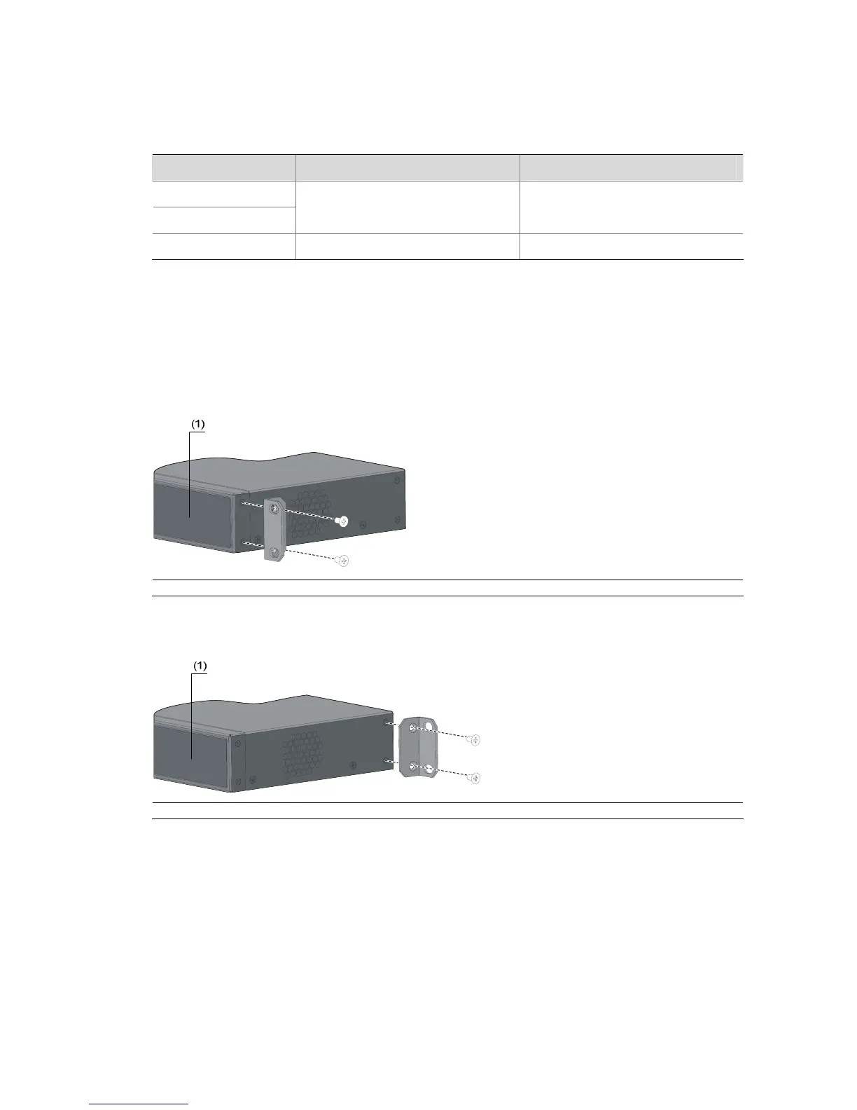
Step1 Place the L2 side of a mounting bracket to the switch and align the mounting holes of the bracket with
the holes of the chassis. See
Figure 3-4 and Figure 3-5 when installing a two-holed mounting bracket,
and
Figure 3-6 and Figure 3-7 when installing a four-holed mounting bracket.
Step2 Fasten the screws.
Figure 3-4 Install a two-holed mounting bracket on the chassis (front part)
(1) Front panel
Figure 3-5 Install a two-holed mounting bracket on the chassis (rear part)
(1) Front panel

 Loading...


