Figure 14 Vertical alignment of the sensor with SVS
1 Spacer 3 SVS sensor (optional)
2 Distance from interior crown of pipe to top of frame
5.1.2.6 Align the sensor horizontally
The sensor must be aligned horizontally to make sure that the sensor is over the center of the flow. If
the pipe is not level and has a slope of 2 degrees or more, align the sensor to be parallel with the
surface of the water.
Item to collect: Bubble level
1. Remove the paper backing from the bubble level and attach the level to the sensor. Refer to
Figure 12 on page 18.
2. Loosen the clamps and tap the frame into position.
3. Tighten both clamps and measure the frame position to make sure that it is at the correct
position.
5.1.2.7 Make a final alignment check
The correct vertical and horizontal alignment of the sensor is necessary for accurate measurements.
1. Measure the vertical alignment and make adjustments if necessary. Refer to Align the sensor
vertically – Flo-Dar without SVS on page 18 or Align the sensor vertically – Flo-Dar with SVS
on page 19.
2. Measure the horizontal alignment and make adjustments if necessary. Refer to Align the sensor
horizontally on page 20.
3. Repeat steps 1 and 2 until no further adjustments are necessary.
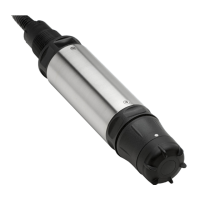
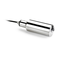
5.1.2.8 Optional extended range sensor installation
The extended range sensor (Figure 15) can be used when the pipe or channel depth is more than
the standard level specifications. Refer to Specifications on page 3.
Use the extended frame (Figure 16) instead of the standard frame, or mount the extended range
sensor on the wall.
The extended range sensor must be installed at least 457.2 mm (18 in.) above the crown of the pipe
for correct measurements. The extended range sensor has a deadband zone of 431.8 mm (17 in.)
where the sensor is not active.
20
English

 Loading...