13
Installation
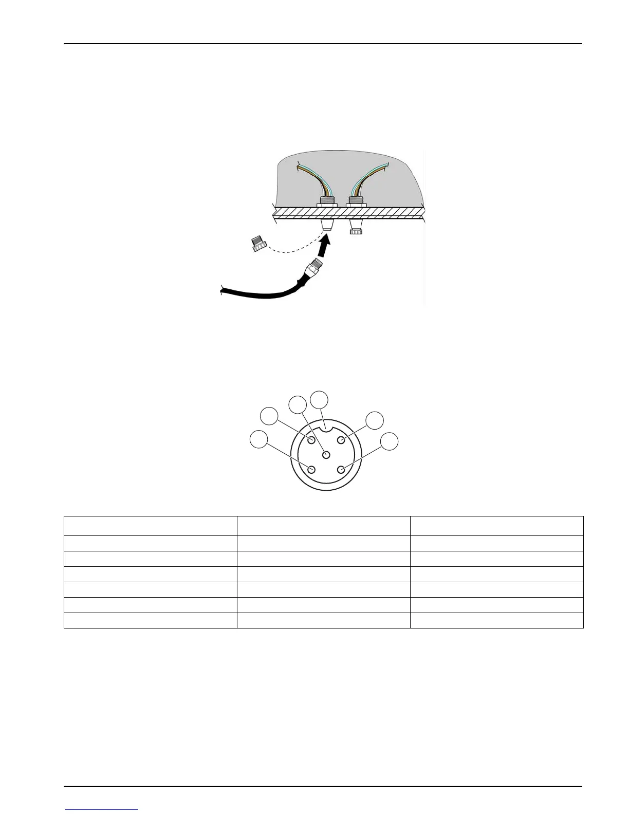
2. Insert the connector in the socket and hand-tighten the union nut.
Note: The middle connection of a sc1000 controller is solely reserved for the display module.
Note: Optional cables may be purchased to extend the sensor cable length (see Section 8 on
page 31).
Figure 6 Attach the sensor to the controller with the quick-connect fitting
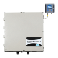
Figure 7 Sensor connector pin assignment
Terminal number Terminal description Wire color code
1+12 VDCbrown
2 Mass/Circuit common black
3Data (+)blue
4 Data (–) white
5 Screen/Shield Screen/Shield (grey)
6 Notch —