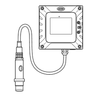
Figure 2 Product components
1 Sensor body 4 Calibration cap 7 Electrode
2 Flow chamber, stainless steel 5 Membranes (4x) 8 SC4500 Controller
3 Syringe for electrolyte, 5 mL 6 Sensor cable, 10 m (33 ft) 9 Cable gland, M16
Section 3 Installation
C A U T I O N
Multiple hazards. Only qualified personnel must conduct the tasks described in this section of the
document.
3.1 Installation guidelines
• Put the instrument in a location that has access for operation, service and calibration.
• Make sure that there is good view of the display and controls.
• Keep the instrument away from a heat source.
• Keep the instrument away from vibrations.
• Keep the sample tubing as short as possible to minimize the response time.
• Make sure that there is no air in the sample supply line.
English
7
 Loading...

