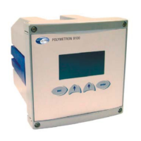
Transmitter 9135 - pH/redox measurement
Page 22
Relation between colour-function
The following table defines the relation between the
types of cable and their functions.
NC : for non combined electrodes
C : for combined electrodes
+ V - V Input Ref Temp
+
Temp-
Liq.
Earth
GND Earth
terminal*
2654
NC
- - (1) Red white purple
(3) (4)
2654 C - - (1) (3') white purple
- (4)
2666 brown grey green yellow
white pink - *** (4)
8366 brown white green yellow
grey ** ** - (4)
8350.0/
1/2
- - (1)
clear
(3')
black
white red - - (4)yellow
/green
8350.4 - - (1)
clear
(3')
black
white red blue - (4)yellow
/green
8351 - - (1)
clear
(3')
black
- - - - (4)yellow
/green
8361 (
pH +
temp
cables)
- - (1)
black
(3')
white
white red blue - (4)yellow
/green
AS9
NC
- - (1) - - - - (3) (4)
AS9 C - - (1) (3') - - - - (4)
AS7 - - - (2) - - - - (4)
8497 - - - - white green blue - (4)
8663 brown white green - - - - yellow
(4) black
* The earth terminal located on the shielded
plate (see figure 2-1) should be connected to
the cable external shield. This connection
should be as short as possible.
** In case of direct link between 8366-transmitter,
realize a solder bridge GND-TEMP(-)-REF.
*** Connect GND to REF in the transmitter if
connection of the 08350=A=8000 preamplifier.
 Loading...
