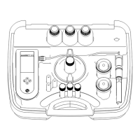
Figure 7 Sample flow through the conditioning kit
1 Sample flow 4 Bypass tee, unfiltered sample 7 Unfiltered-sample ball valve
(shown open)
2 Bypass flow 5 Flow observation point 8 Low-flow valve option
3 Drainage flow 6 Filtered-sample bypass ball
valve (shown open)
9 High-flow valve option
Electrical installation
D A N G E R
Electrocution hazard. Always remove power to the instrument before making electrical connections.
Remove the access cover
Remove the access cover to connect to the wiring terminals. Refer to Figure 8.
12
English

 Loading...